
Sunlight simulator

a solar cell and simulator technology, applied in the field of solar cell simulator and solar cell measuring device, can solve the problems of affecting the output feature of the solar cell, affecting the cost of manufacture, etc., and achieve the effect of avoiding the use of the splitting uni

Inactive Publication Date: 2012-02-02
CHROMA ATE
View PDF6 Cites 10 Cited by
  • Summary
  • Abstract
  • Description
  • Claims
  • Application Information

AI Technical Summary

Benefits of technology

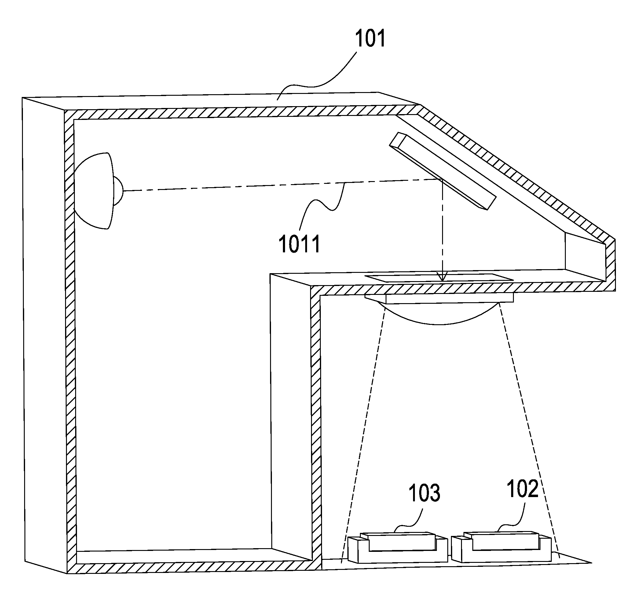
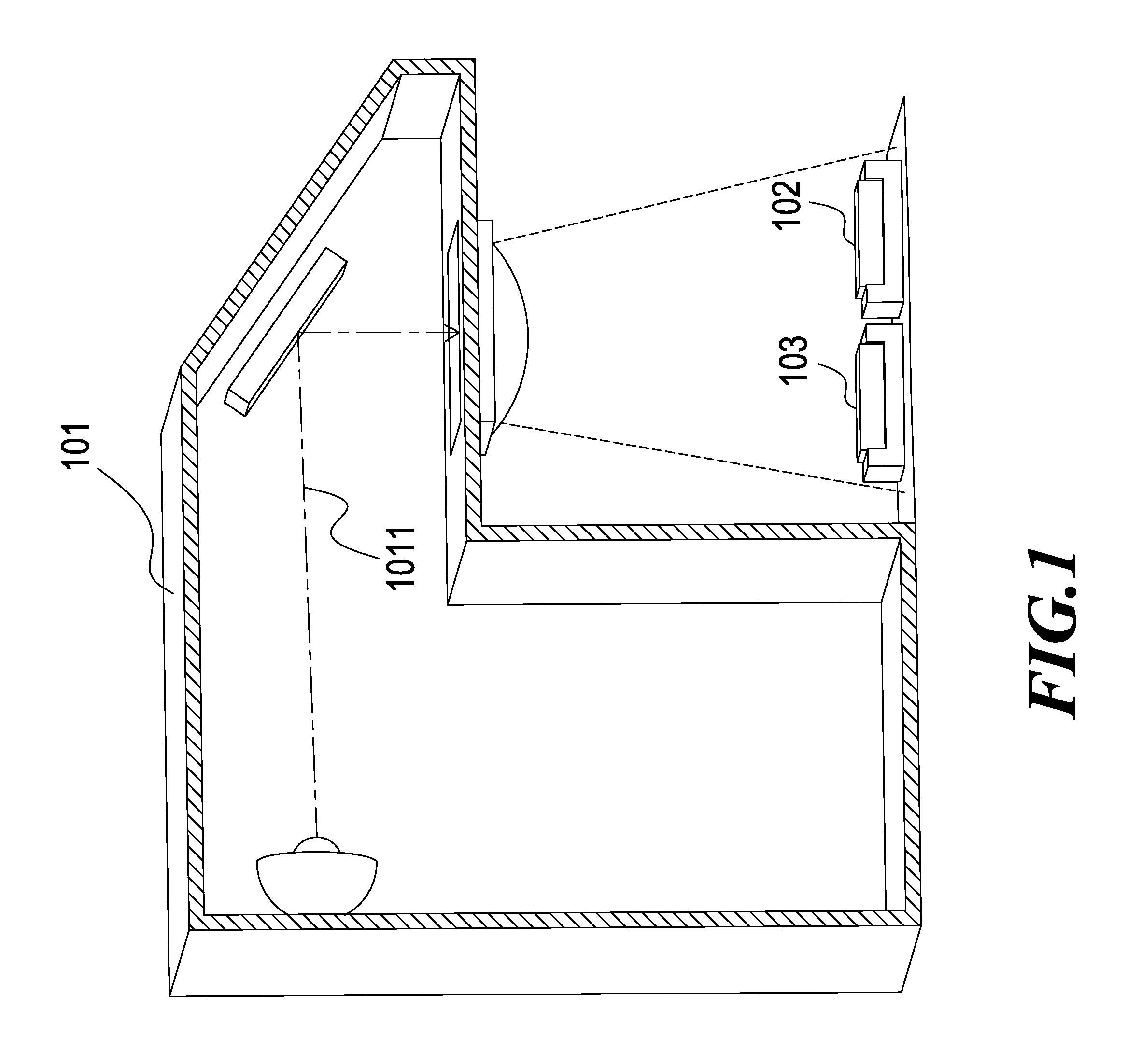
[0011]Yet another objective of the present invention is to provide a sunlight simulator and solar cell measuring device consisting of detecting device which allows to reduce the range of the opening gate and to prevent the use of the high-power light source featuring wider illumination range thereby lessening the manufacture cost for the sunlight simulator or the solar cell measuring device.
[0012]In order to achieve the objectives set forth as above, a sunlight simulator and solar cell measuring device consisting of detecting device according to the present invention is provided wherein the housing is a closed space consisting of an opening gate, the closed space is internally installed with a light source which is used to emit a light toward the opening gate, and a splitting unit is installed on the travelling path of the light for dividing the light into a first light-beam and a second light-beam, herein the first light-beam is projected toward the opening gate, and a collimating lens can be installed at the location of the opening gate for projecting the first light-beam onto the solar cell under measurement as a solar cell measuring device; in addition, a detecting device is installed on the travelling path of the second light-beam for receiving the second light-beam, then a signal can be outputted by the detecting device in order to monitor the intensity of the light emitted by the light source thereby ensuring the precision of solar cell measurement.
[0015]Specifically, an integrating device is installed between the above-said light source and detecting device which allows the light emitted by the light source to become uniform.
[0020]Furthermore, another implementation approach can be also applied in which a transmission detecting device is directly installed on the travelling path of the light of the light source, the surface of the transmission detecting device is installed with a detecting component used to detect light signal and to convert the light signal into a conversion signal for output thereby detecting the irradiation of the light and accordingly eliminating the use of the splitting unit as illustrated in the previous embodiment.

Problems solved by technology

However, in the above-mentioned beam irradiation measurement, since it is necessary to simultaneously project the beam onto the solar cell under measurement and the monitor cell, such an operation needs at least two opening gates or otherwise one single bigger opening gate, thus consequently, forcing the sunlight simulator to use an internal light source of higher power so as to provide sufficiently uniform light radiation onto both the solar cell under measurement and the monitor cell, which adversely affects the output feature of the solar cell.
In addition, since the price for such a type of light source may be proportional to the effective brightness and illumination area thereof, the manufacture cost becomes a disadvantageous factor in such an approach.

Method used


Image

  • Sunlight simulator
  • Sunlight simulator
  • Sunlight simulator

Examples


first embodiment

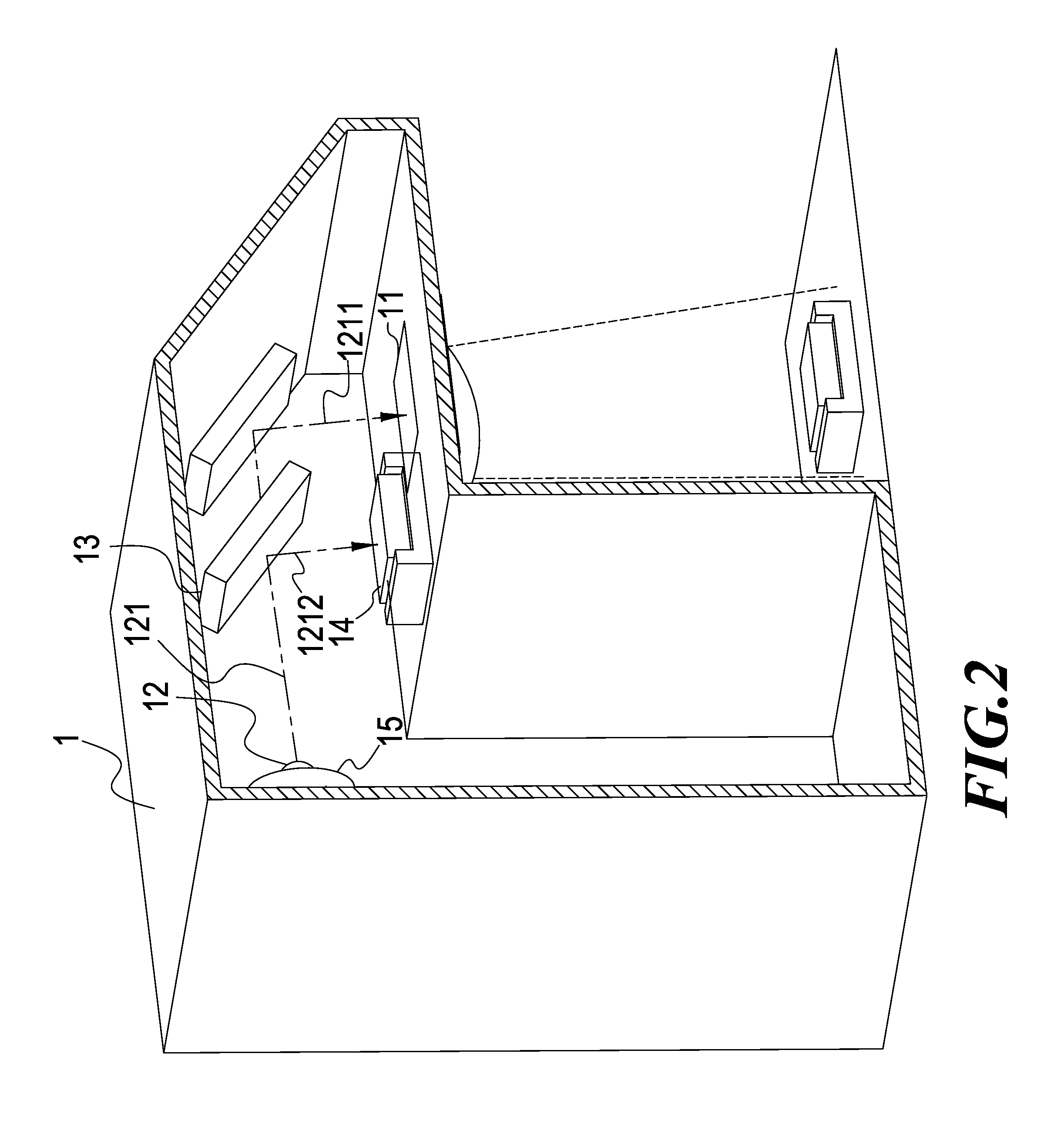
[0031]Refer first to FIG. 2, wherein a diagram for the operation of a sunlight simulator and solar cell measuring device consisting of detecting device according to the present invention is shown. From the Figure, it can be seen that the sunlight simulator comprises:

[0032]a housing 1, which is a closed space consisting of an opening gate 11;

[0033]a light source 12, which is installed inside of the housing 1 for consistently emitting a light 121 toward the opening gate 11 and formed by any one of a set of light emitting diodes (LEDs), a xenon lamp, a halogen lamp or a combination thereof;

[0034]a splitting unit 13, which is installed on the travelling path of the light 121 emitted by the light source 12 for dividing the light 121 into a first light-beam 1211 and a second light-beam 1212, herein the first light-beam 1211 is projected toward the opening gate 11, and additionally the splitting unit 13 is a planar splitter;

[0035]a detecting device 14, which is installed on the travelling ...

second embodiment

[0037]Refer next to FIGS. 3A and 3B, wherein diagrams for the structure and the operation of a sunlight simulator and solar cell measuring device consisting of detecting device according to the present invention are respectively shown. From these Figures, it can be seen that the solar cell measuring device outputs a simulated light source to a solar cell under measurement 4, and the solar cell measuring device comprises:

[0038]a housing 2, which is a closed space consisting of an opening gate 21;

[0039]a light source 22, which is installed inside of the housing 2 for consistently emitting a light 221 toward the opening gate 21 and formed by any one of a set of light emitting diodes (LEDs), a xenon lamp, a halogen lamp or a combination thereof;

[0040]a splitting unit 23, which is installed on the travelling path of the light 221 emitted by the light source 22 for dividing the light 221 into a first light-beam 2211 and a second light-beam 2212, and additionally the splitting unit 23 is a...

fourth embodiment

[0050]Refer now to FIG. 4A, wherein a diagram for the operation of a sunlight simulator and solar cell measuring device consisting of detecting device according to the present invention is shown. From the Figure, it can be seen that the sunlight simulator comprises:

[0051]a housing 5, which is a closed space consisting of an opening gate 51;

[0052]a light source 52, which is installed inside of the housing 5 for consistently emitting a light 521 toward the opening gate 51 and formed by any one of a set of light emitting diodes (LEDs), a xenon lamp, a halogen lamp or a combination thereof;

[0053]a transmission detecting device 53, which is installed on the travelling path of the light 521 emitted by the light source 52 for receiving the light 521 and allows the light 521 to pass through the transmission detecting device 53. A detecting component is installed on the surface of the transmission detecting device 53 thereby monitoring the irradiation of the light 521 emitted by the light so...


PUM


Abstract

A sunlight simulator and solar cell measuring device consisting of detecting device is disclosed, in which the housing is a closed space consisting of an opening gate, the closed space is internally installed with a light source which is used to emit a light toward the opening gate, and a splitting unit is installed on the travelling path of the light for dividing the light into a first light-beam and a second light-beam, herein the first light-beam is projected onto the solar cell under measurement located at the opening gate as a solar cell measuring device; in addition, a detecting device is installed on the travelling path of the second light-beam for receiving the second light-beam, and then a signal can be outputted by the detecting device in order to monitor the irradiation variation of the light emitted by the light source, thus ensuring the precision of the solar cell measurement.

Description

BACKGROUND OF THE INVENTION[0001]1. Field of the Invention[0002]The present invention generally relates to a sunlight simulator and solar cell measuring device consisting of detecting device; in particular, the present invention relates to a sunlight simulator or a solar cell measuring device internally equipped with a detecting device thereby monitoring the irradiation intensity of a beam emitted by an internal light source.[0003]2. Description of Related Art[0004]At present, the solar cell power generation system is produced by means of semiconductor processes, whose power generation principle lies in that solar daylight is allowed to radiate on the solar cell such that the solar cell absorbs the incident sunlight energy thereby generating electron to create current due to semiconductor features, and transferring the created current to the load via conducting lines.[0005]Therefore, after completion of solar cell manufacture processes, it is required to evaluate the performance of ...

Claims


Application Information

Patent Timeline
IPC IPC(8): G01R31/26G01R31/00
CPCF21S8/006
Inventor LEE, CHING-LINCHANG, I-FANLIN, MING-CHIEH
Owner CHROMA ATE
Learn More