RFID tracking of patient specimen samples

a patient specimen and tracking technology, applied in the field of medical laboratory testing and specimen handling, can solve the problems of difficult physical location of a particular sample among a large population of samples, limitation of the range in which could be read, and limitation of the cost effectiveness of the limitation system,

Inactive Publication Date: 2012-02-02
BOLANDER JARIE G +2
View PDF1 Cites 48 Cited by
  • Summary
  • Abstract
  • Description
  • Claims
  • Application Information

AI Technical Summary

Benefits of technology

[0011]In the laboratory, each specimen is tracked as needed. Multiple readers in the laboratory can be set to constantly read and report specimen location by determining the time of arrival for each read'tag (which will give triangulation information) and the power node which powered the tag (nodes operating at different times, e.g. in sequence). The reader antennas can be in a fixed position, or they can be rotating around directionally to read selectively certain areas. The system can employ time delay of arrival (TDOA) of the responsive signals, or a receive signal strength indicator (RSSI), or both, as well as variable power-up power (as from differently located nodes) to determine the distance from the reader emitting the power beam. Multiple antennas can form a beam that can be targeted to specific regions. There can be multiple antenna arrays of this nature with the controller for these arrays sending beam location back to the reader. Further, a person with a hand-held reader also can walk around the laboratory to find a specific specimen. The user is prompted on which way to proceed via the hand-held's data link back to the reader or tracking software. Any particular specimen is easily located among hundreds or even thousands of specimens in the laboratory using this system. A feature of the invention is that the hand-held device can have a power node for powering the passive RFID tags, from a close range of normally a few inches. The specimens are within range of a reader in the laboratory or other storage facility. With the hand-held the user turns on the power node to power a selected one or a small group of specimen tags causing them to be read by the reader. This enables verification or location of individual specimens when desired.

Problems solved by technology

Another problem is that even with a sample in the proper location, it is difficult to physically locate a particular sample among a large population of samples.
Previous specimen tracking systems employing RFID tags have had a fundamental limitation on the range in which could be read.
This limitation did not allow for the reading of specimens in bulk nor did it allow for cost effective locations systems, which is critical for a cost effective sample tracking and location system.

Method used


Image

  • RFID tracking of patient specimen samples
  • RFID tracking of patient specimen samples
  • RFID tracking of patient specimen samples

Examples


Embodiment Construction

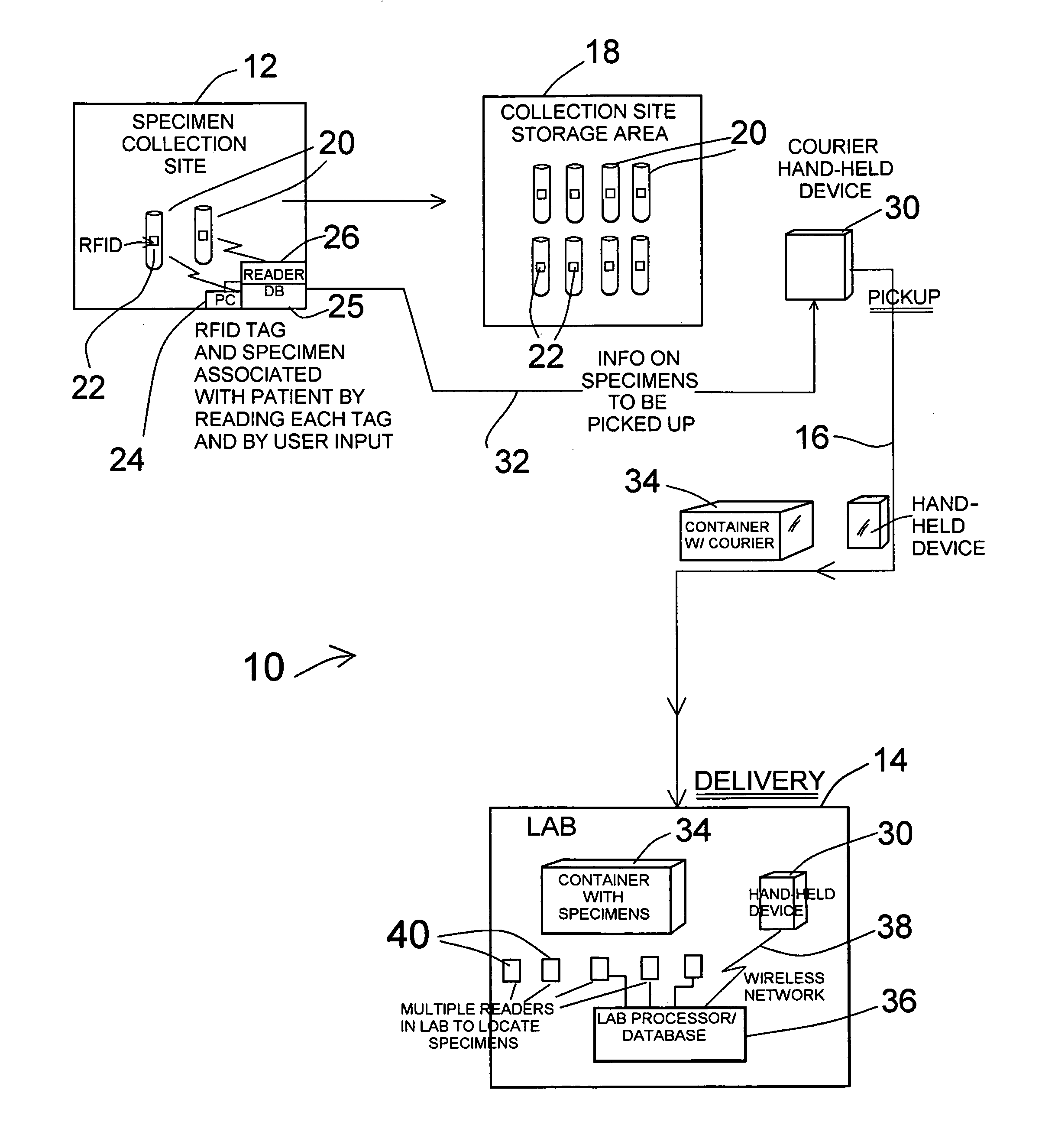
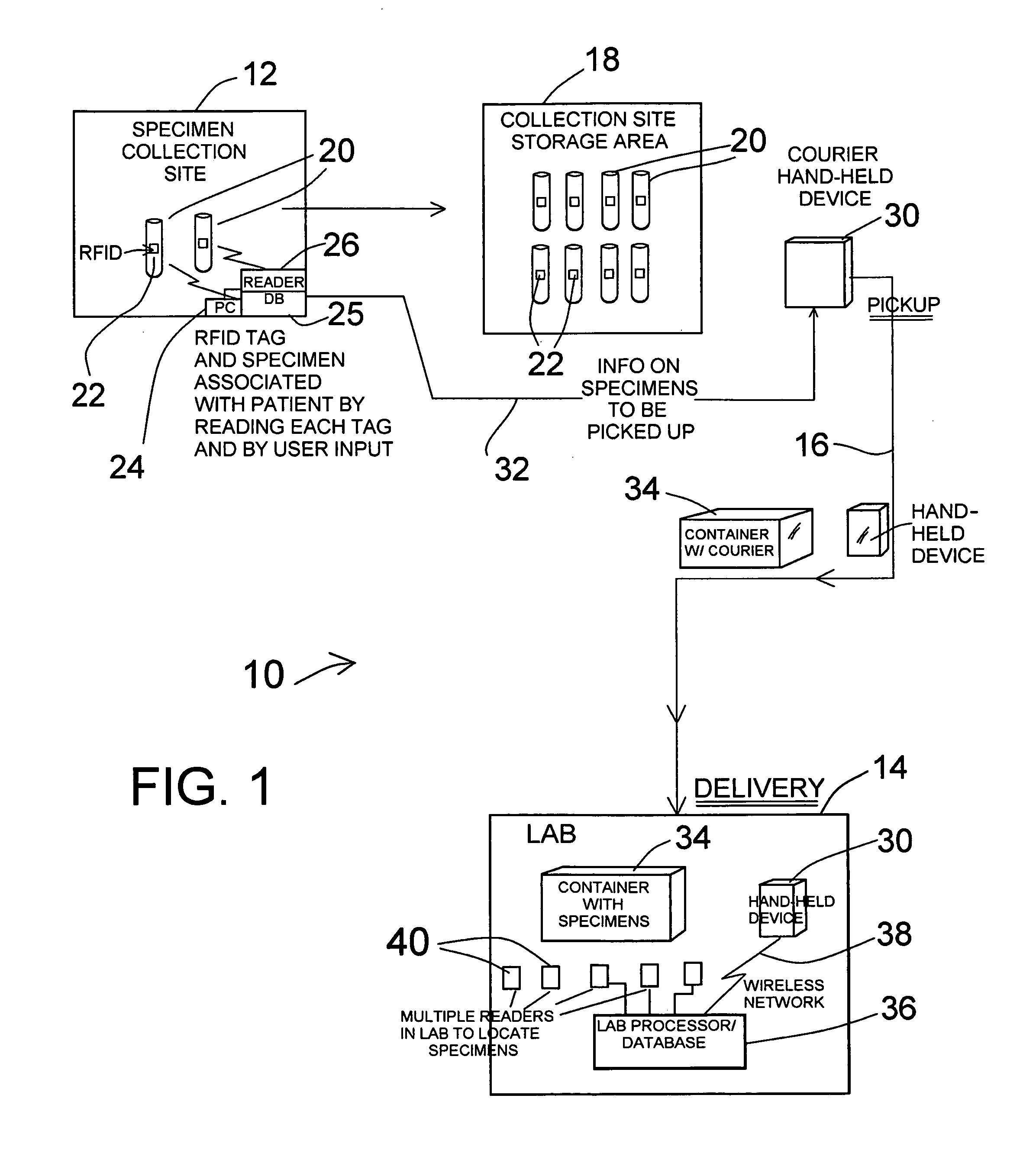
[0018]In the drawings, FIG. 1 shows schematically a specimen tracking system 10 which includes a specimen collection site 12 and a specimen testing laboratory 14 normally (but not necessarily) located remotely from the collection site. A transportation path from the collection site 12 to the laboratory 14 is shown at 16.

[0019]At the specimen collection site 12 a storage area 18 is included. Patient samples, such as blood, are collected in vessels 20, which can be the typical small tubes used for such purposes. Specimens are collected and placed in the collection site storage area 18, as indicated in this schematic illustration.

[0020]Pursuant to the invention a small RFID tag at 22 is secured to each specimen collection vessel 20. Immediately after each specimen is taken and enclosed in the vessel, the patient information for this particular specimen is associated with the RFID tag 22 on the vessel. For example, this may be done using a personal computer (PC) 24 at the collection sit...


PUM


Abstract

Miniature RFID tags are used in a system for identifying, locating, tracking and inventorying patient specimens pursuant to medical testing. The RFID tags are attached to specimen vessels, and at a point of collection for patient specimens each RFID tag of a vessel is associated with patient and test data, in a collection site database. When a series of vessels are to go to a laboratory, a hand-held device receives all data on the specimens via download from the collection site PC/database. A courier picks up a container with the specimen vessels and delivers it to the laboratory, along with the hand-held device. At the lab a reader reads all specimen tags, and the data stored in the hand-held device is downloaded to a lab processor/database to verify all specimens are present. Location of specimens can be done by reading or powering up different zones, and the hand-held device can have a power node for selectively powering one or several specimen tags for identification or location of specific specimens.

Description

BACKGROUND OF THE INVENTION[0001]This invention concerns medical laboratory testing and specimen handling, and specifically encompasses the use of miniature RFID tags, usually of the passive type but sometimes of the active type, for tracking, locating, identifying and inventorying patient specimen samples, such as tissue, blood or other fluids.[0002]Conventionally, patient specimen vessels have been identified using labels attached to each specimen vessel, the labels each carrying patient and specimen information and all relevant data, and sometimes bearing a bar code as an identifier, to be linked with a database connected to a bar code reader. Usually specimens are taken at one location and transported to another for analysis and testing. The specimens can become lost, misplaced or de-labeled, and they are generally not accounted for other than at the point of taking the specimen and at the point of testing. Another problem is that even with a sample in the proper location, it is...

Claims


Application Information

Patent Timeline
Patent Type & Authority Applications(United States)
IPC IPC(8): G08B13/14
CPCG06F19/366G06Q10/08G16H10/40
Inventor BOLANDER, JARIE G.WUNDERLICH, FORRESTPALEY, DANIEL
Owner BOLANDER JARIE G
Why Eureka
Try Eureka