USB Flash Drive With Deploying And Retracting Functionalities Using Retractable Cover/Cap

Inactive Publication Date: 2012-02-02
SUPER TALENT ELECTRONICS
View PDF2 Cites 16 Cited by
  • Summary
  • Abstract
  • Description
  • Claims
  • Application Information

AI Technical Summary

Benefits of technology

[0014]According to another embodiment of the present invention, a method for assembling a portable computer peripheral apparatus includes fixedly connecting a printed circuit board assembly (PCBA) onto an elongated housing consisting entirely of one or more integrally molded plastic structures, and then mounting a cap/cover onto a front portion of the housing, wherein the cap/cover comprising an integrally molded stru

Problems solved by technology

A problem with convention pen-type peripheral devices is that the removable cover can become inadvertently

Method used


Image

  • USB Flash Drive With Deploying And Retracting Functionalities Using Retractable Cover/Cap
  • USB Flash Drive With Deploying And Retracting Functionalities Using Retractable Cover/Cap
  • USB Flash Drive With Deploying And Retracting Functionalities Using Retractable Cover/Cap

Examples


Embodiment Construction

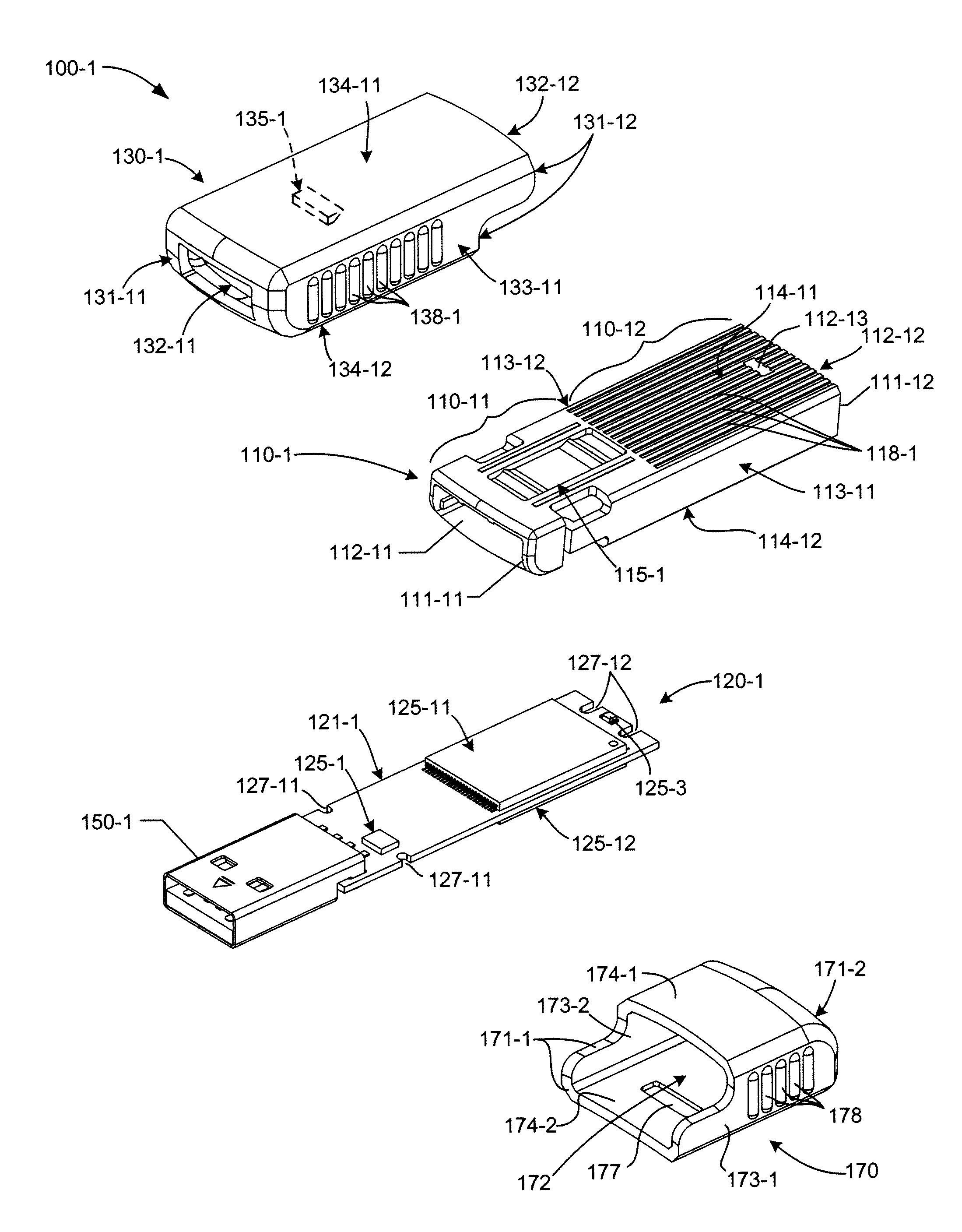
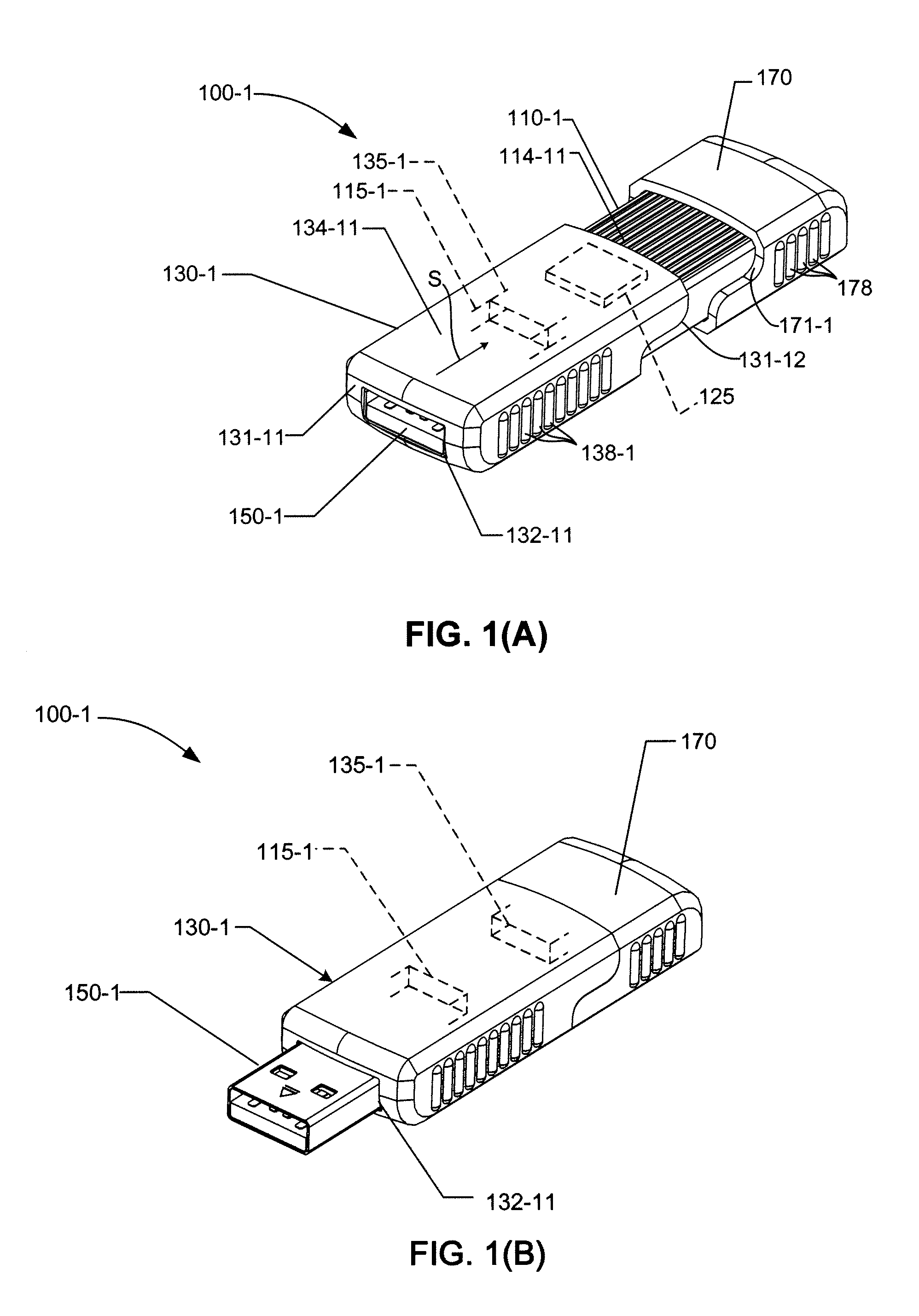
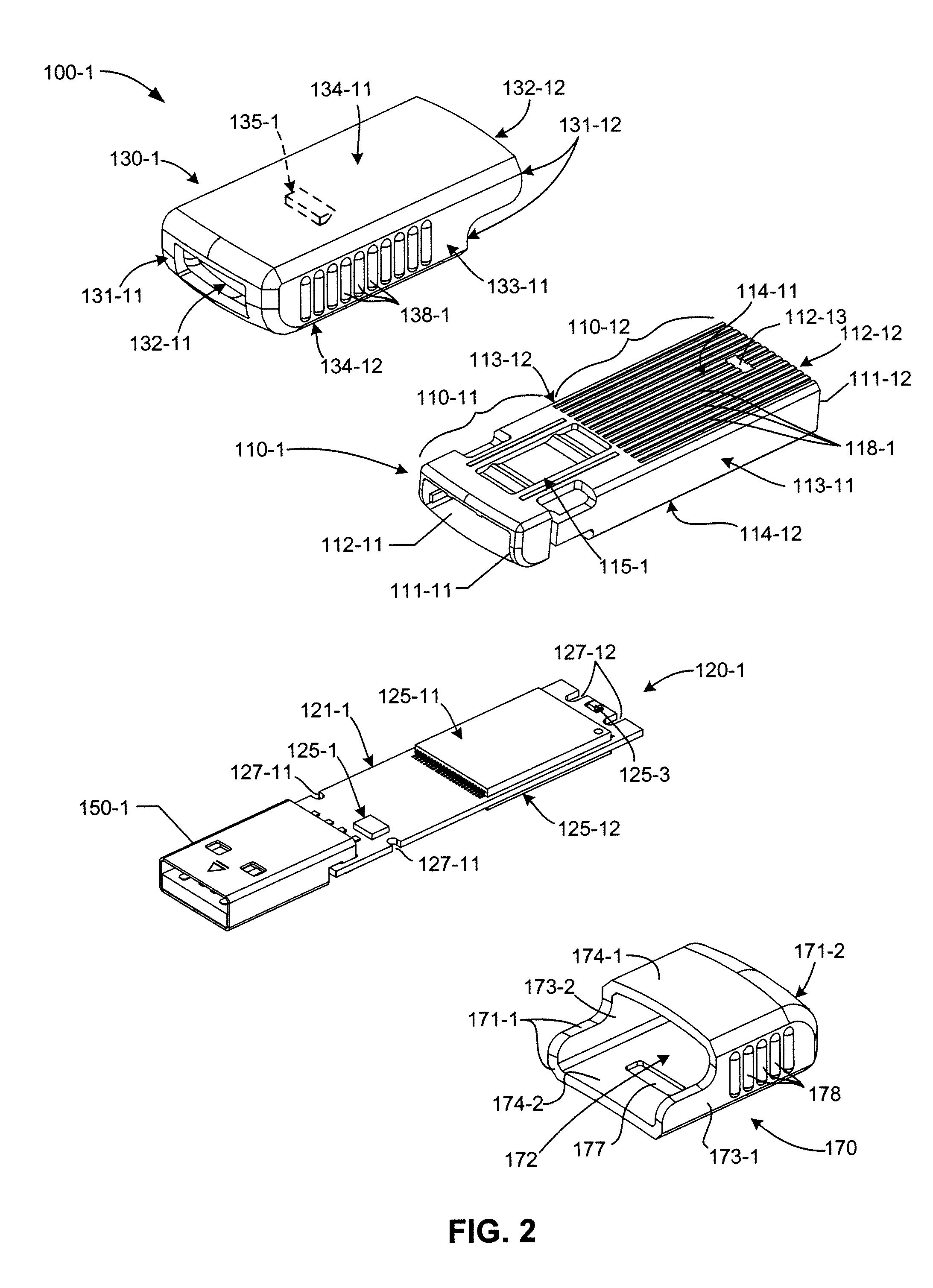
[0027]The present invention relates to an improvement in low-cost computer peripheral devices. The following description is presented to enable one of ordinary skill in the art to make and use the invention as provided in the context of a particular application and its requirements. As used herein, directional terms such as “upper”, “upward”, “lower”, “downward”, “front”, “rear”, are intended to provide relative positions for purposes of description, and are not intended to designate an absolute frame of reference. In addition, the phrases “integrally connected” and “integrally molded” are used herein to describe the connective relationship between two portions of a single molded or machined structure, and are distinguished from the terms “connected” or “coupled” (without the modifier “integrally”), which indicates two separate structures that are joined by way of, for example, adhesive, fastener, clip, or movable joint. Various modifications to the preferred embodiment will be appa...


PUM

PropertyMeasurementUnit
Heightaaaaaaaaaa

Abstract

A pen-type computer peripheral device includes an elongated housing containing a PCBA having a plug connector, and cap/cover that is slidably connected to a front portion of the housing. Locking structures are respectively integrally molded onto opposing surfaces of the housing and cap/cover that cooperate to prevent separation of the cap/cover from the housing. By manually pushing (sliding) the cap/cover relative to the housing, the plug connector is effectively moved between a retracted position, in which the plug connector is disposed inside the cap/cover, and a deployed position in which the plug connector extends through a front housing opening of the cap/cover such that the plug connector is operably exposed for insertion into a host system.

Description

RELATED APPLICATIONS[0001]This application is a continuation in part of U.S. patent application for “PRESS / PUSH USB FLASH DRIVE WITH DEPLOYING AND RETRACTING FUNCTIONALITIES WITH ELASTICITY MATERIAL AND FINGERPRINT VERIFICATION CAPABILITY”, U.S. application Ser. No. 11 / 845,747, filed Aug. 27, 2007, which is a continuation in part of U.S. patent application for “ELECTRONIC DATA STORAGE MEDIUM WITH FINGERPRINT VERIFICATION CAPABILITY”, U.S. application Ser. No. 09 / 478,720, filed Jan. 6, 2000, which has been petitioned claiming benefit of Continuation-In-Process status of one of inventor's earlier U.S. patent application for “INTEGRATED CIRCUIT CARD WITH FINGERPRINT VERIFICATION CAPABILITY”, U.S. application Ser. No. 09 / 366,976, filed Aug. 4, 1999, now issued as U.S. Pat. No. 6,547,130.[0002]This application is also a continuation in part of U.S. patent application for “USB PACKAGE WITH BISTABLE SLIDING MECHANISM”, Ser. No. 12 / 552,250, filed Sep. 1, 2009.[0003]This application relates ...

Claims


Application Information

Patent Timeline
IPC IPC(8): G06F1/16H05K13/00
CPCG06F21/86G06F21/32G06F2221/2153G06K9/0002G06F21/85G06K19/07732Y10T29/49002G06V40/1306
Inventor NI, JIM CHIN-NANMA, ABRAHAM C.
Owner SUPER TALENT ELECTRONICS
Why Eureka
Try Eureka