Medical image diagnostic apparatus and volume calculating method

a diagnostic apparatus and image technology, applied in the field of medical image diagnostic apparatus and volume calculation method, can solve problems such as volumeter calculation errors in the heart chamber, and achieve the effect of improving the accuracy of volume calculation of an organ

Active Publication Date: 2012-02-02
FUJIFILM HEALTHCARE CORP
View PDF26 Cites 30 Cited by
  • Summary
  • Abstract
  • Description
  • Claims
  • Application Information

AI Technical Summary

Benefits of technology

[0025]The present invention can provide the medical image diagnostic apparatus and volume calculation method capable of improving accuracy of volume calculation of an organ compared to the conventional Simpson's method.

Problems solved by technology

In other words, there is a problem in the conventional Simpson's method that the difference in distortion degrees of accumulation positions between the disks causes errors in volumeter calculation of the heart chamber.

Method used


Image

  • Medical image diagnostic apparatus and volume calculating method
  • Medical image diagnostic apparatus and volume calculating method
  • Medical image diagnostic apparatus and volume calculating method

Examples


embodiment 1

[0037]The first embodiment will be described in detail using FIG. 1˜FIG. 4.

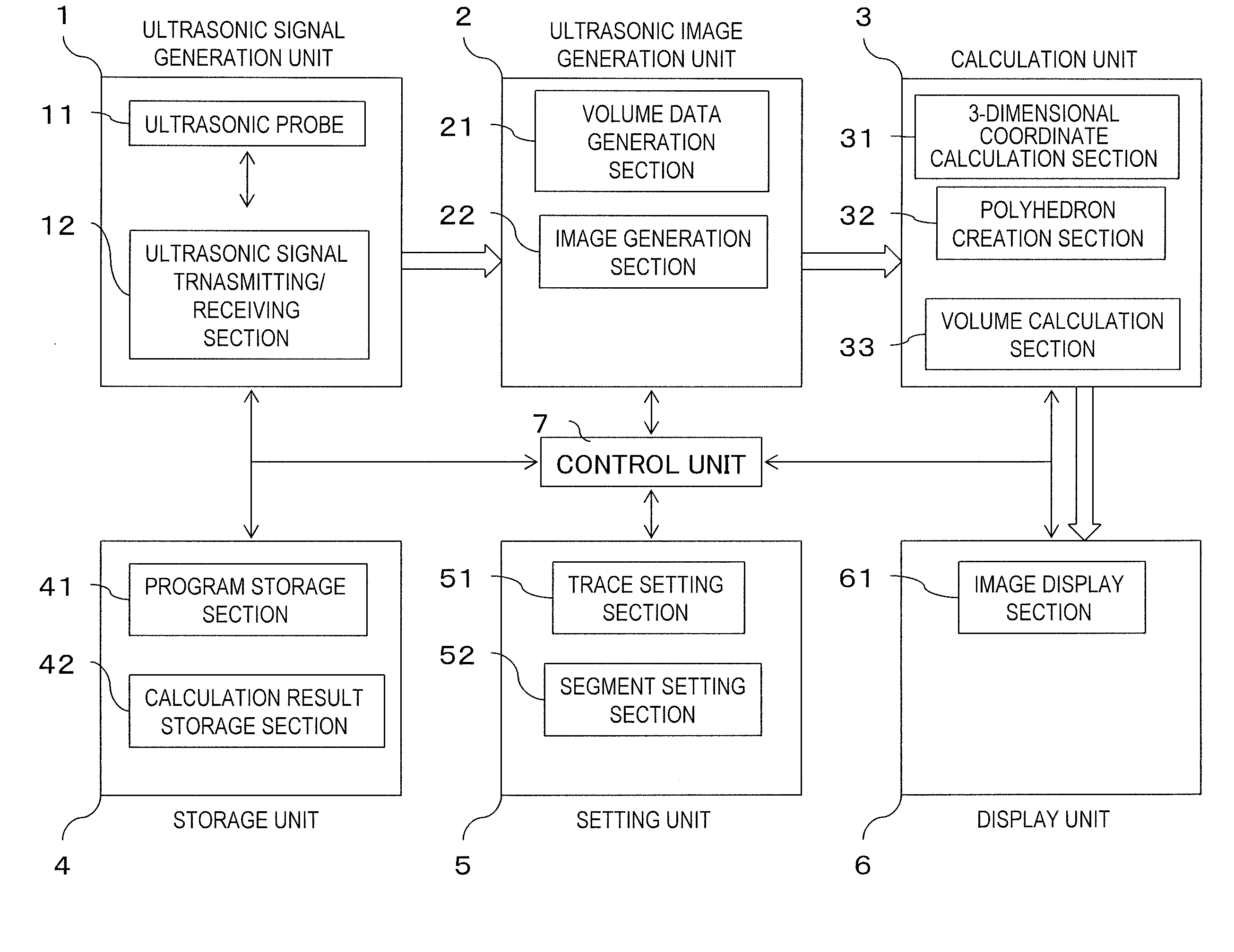
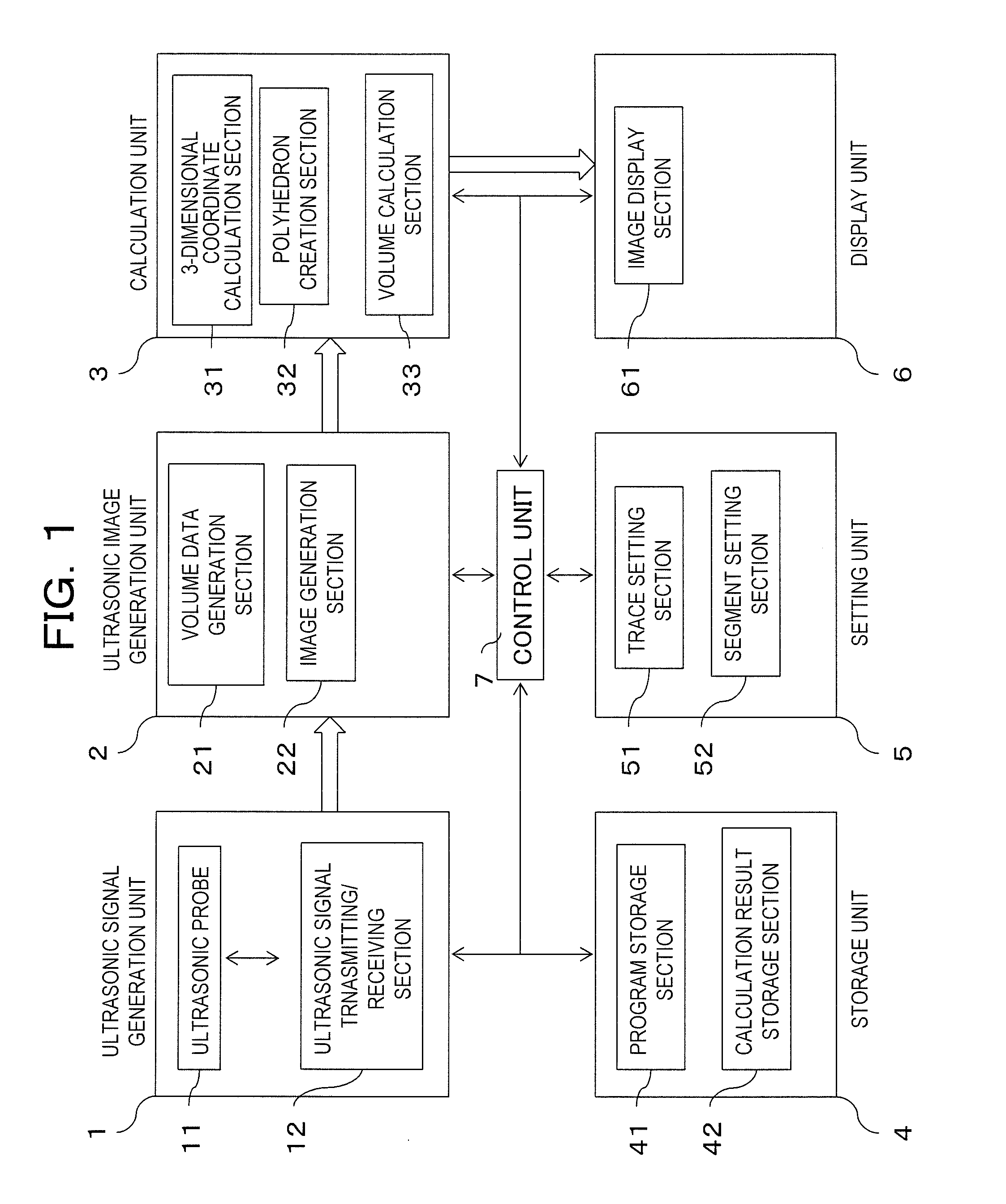
[0038]FIG. 1 is an example of a system configuration diagram of the ultrasonic image diagnostic apparatus.

[0039]The ultrasonic diagnostic signal generation unit 1 comprises an ultrasonic probe 11 and an ultrasonic signal transmission / reception section 12, for transmitting an ultrasonic signal to the object and acquiring the reflected echo signal from the object.

[0040]The ultrasonic probe 11 comprises transducer elements having a scan method such as the linear type, convex type or sector type and capable of transmitting / receiving ultrasonic waves and arrayed in at least one-dimensional direction. The ultrasonic probe 11 is to be applied directly to an object so as to acquire ultrasonic signals of the object by transmission and reception of ultrasonic waves. An example of the ultrasonic probe 11 is a 2D-array probe in which the transducer elements capable of transmitting and receiving ultrasonic waves are 2-dim...

embodiment 2

[0086]The second embodiment will be described in detail using FIG. 5 and FIG. 6.

[0087]The same ultrasonic diagnostic apparatus as the first embodiment will be exemplified below.

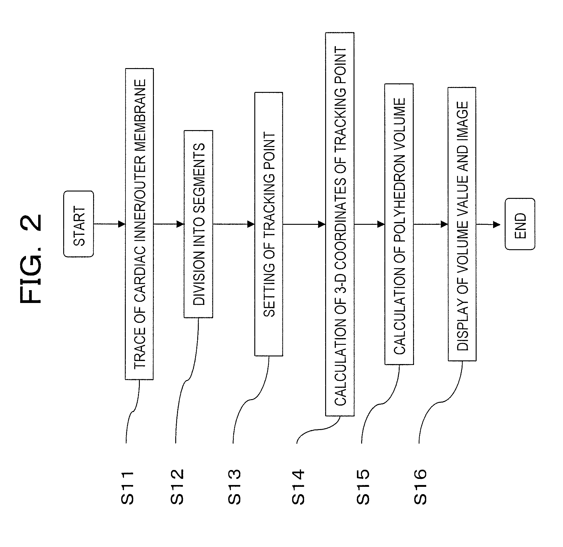
[0088]An example of measurement process by the ultrasonic diagnostic apparatus in the second embodiment related to the present invention will be described using the flowchart shown in FIG. 5. FIG. 5 is the flowchart showing measurement process by the ultrasonic diagnostic apparatus in the second embodiment related to the present invention.

[0089](Step S21)

[0090]The examiner applies the ultrasonic probe 11 of the ultrasonic signal generation unit 1 to an object, and generates ultrasonic signals by scanning a 2-dimensional image or 3-dimensional image of the object's heart. The control unit 7 reads in the 3-dimensional ultrasonic image generated by the volume data generation section 21 to the calculation result storage section 42 from the ultrasonic signal generated by the ultrasonic signal generation unit 1, an...

embodiment 3

[0103]The third embodiment explains an example for diagnosing a disease using information on volume of an organ acquired by the first embodiment or time change of the volume.

[0104]The third embodiment will be described in detail referring to FIG. 7˜FIG. 10.

[0105]FIG. 7 is an example of a system configuration diagram of the ultrasonic diagnostic apparatus in the third embodiment related to the present invention.

[0106]In the system configuration diagram of the ultrasonic diagnostic apparatus in the third embodiment, description on the repeated components in the first embodiment will be omitted and only different components will be described.

[0107]To the calculation unit 3 in the third embodiment, a disease estimation section 34 is added to the 3-dimensional coordinate calculation section 31, the polyhedron creation section 32 and the volume calculation section 33.

[0108]The disease estimation section 34 estimates the kind of diseases from time change of the volume values of the left ve...


PUM


Abstract

A medical image diagnostic apparatus provided with an image acquisition unit configured to acquire in-vivo information about an object to be examined as a medical image, a display unit configured to display the medical image, a setting unit configured to set a target region of volume measurement in the medial image displayed on the display unit, a calculation unit configured to perform calculation to split the target region into a plurality of volume elements, calculate the moving distance of the vertices of the volume elements when the target region of the acquired medical image moves, calculate the volumes of the volume elements after the movement using the calculated moving distance of the vertices, totalizing the calculated volumes of the volume elements after the movement and using the total volume as the volume of the target region, and a control unit configured to display the volume of the target region on the display unit.

Description

FIELD OF THE INVENTION[0001]The present invention relates to a medical image diagnostic apparatus and volume calculating method for measuring volume of an organ in a medical image of an organ including a motile organ such as a heart.DESCRIPTION OF RELATED ART[0002]Volume of a heart chamber which is one of the motile organs is calculated by a method referred to as the Simpson's method. The Simpson's method calculates volume of a cardiac chamber, for example in the case of using a medical image, by dividing a volumeter region of the cardiac chamber into a plurality of accumulated cylindrical disks and summing the respective disk volumes. The Simpson's method is disclosed, for example in Patent Document 1 and has been publicly known.PRIOR PATENT DOCUMENTS[0003]Patent Document 1: JP-T-2007-507248[0004]Patent Document 2: JP-A-2006-247203[0005]The inventor conducted verification on the following concrete case in the conventional Simpson's method.[0006]That is, in the case of selecting the...

Claims


Application Information

Patent Timeline
Patent Type & Authority Applications(United States)
IPC IPC(8): G06K9/00
CPCA61B5/02028A61B8/483A61B5/1075A61B6/503A61B8/065A61B8/08A61B8/0883A61B8/463A61B8/466A61B8/5223A61B8/5238G06T7/602G06T17/20G06T2207/30048A61B5/055G06T7/62G16H50/30
Inventor CHONO, TOMOAKI
Owner FUJIFILM HEALTHCARE CORP
Why Eureka
Try Eureka