
Endless belt assembly, fixing device, and image forming apparatus employing same

a technology of fixing device and endless belt, which is applied in the direction of electrographic process apparatus, instruments, optics, etc., can solve the problems of lateral misalignment or displacement of the fuser belt from the desired path of movement, various operational failures, and particularly pronounced problems

Inactive Publication Date: 2012-02-02
RICOH KK
View PDF2 Cites 10 Cited by
  • Summary
  • Abstract
  • Description
  • Claims
  • Application Information

AI Technical Summary

Benefits of technology

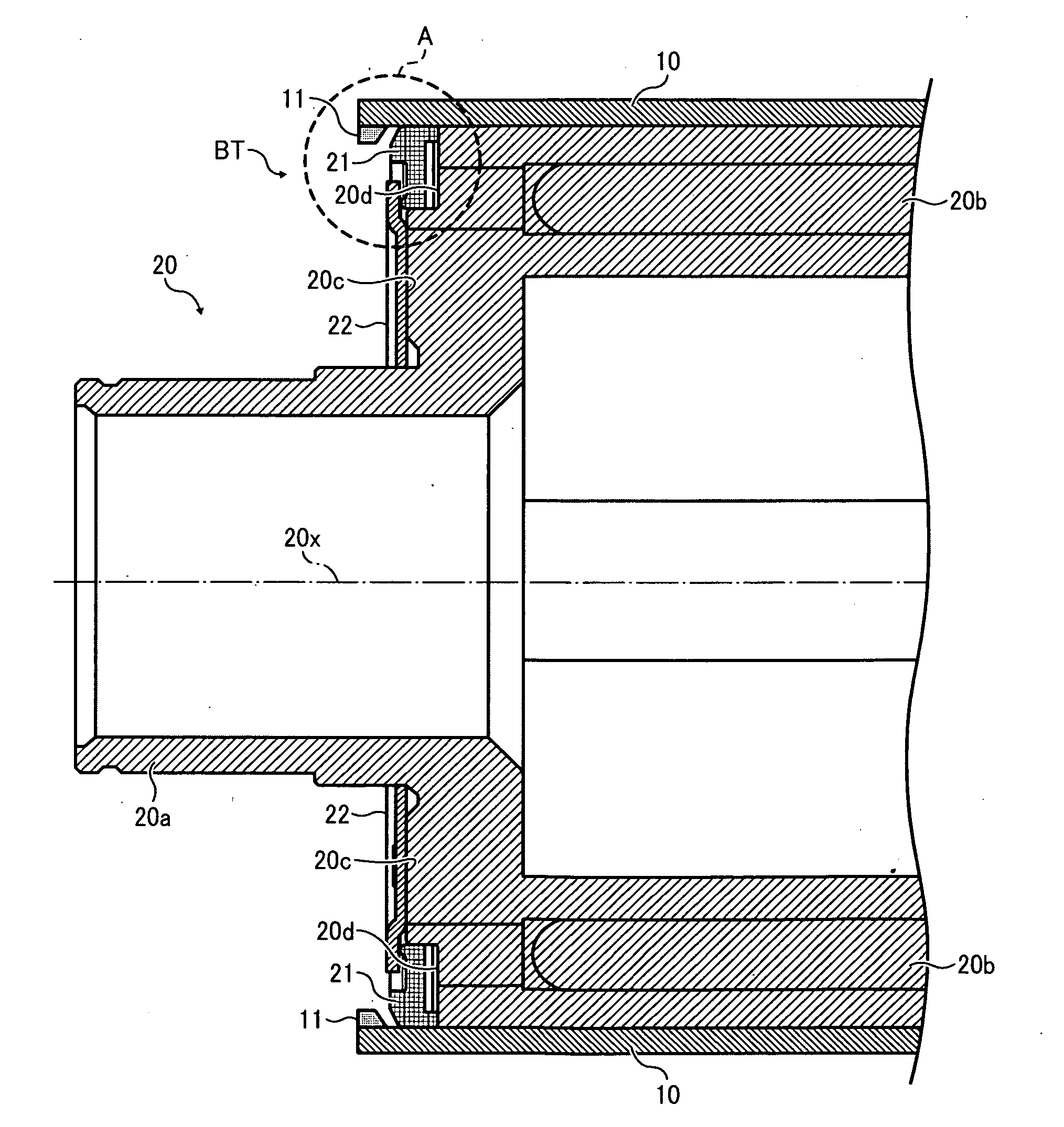
[0015]Still another technique provides an improved belt tracking mechanism similar to that depicted above, wherein the annular friction flange of the support roller and the circumferential edge rib of the endless belt have their interfacing surfaces beveled or inclined to effectively prevent the belt from climbing over the outer circumference of the support roller.
[0015]Still another technique provides an improved belt tracking mechanism similar to that depicted above, wherein the annular friction flange of the support roller and the circumferential edge rib of the endless belt have their interfacing surfaces beveled or inclined to effectively prevent the belt from climbing over the outer circumference of the support roller.
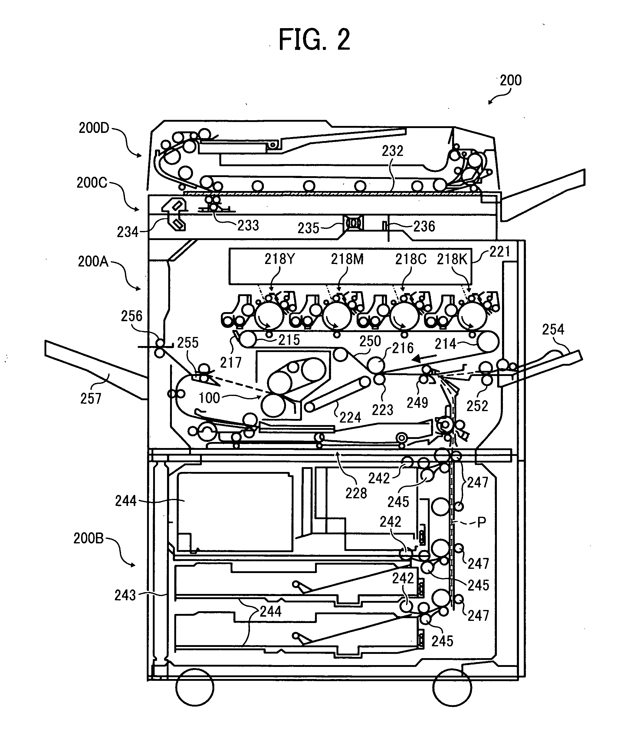
[0003]The present invention relates to an endless belt assembly, a fixing device, and an image forming apparatus employing the same, and more particularly, to an endless belt assembly including an endless looped belt entrained around multiple rollers applicable to a fixing device that fixes a toner image in place on a recording medium with heat and pressure, and an electrophotographic image forming apparatus, such as a photocopier, facsimile machine, printer, plotter, or multifunctional machine incorporating several of those imaging functions, employing such an endless belt assembly.

Problems solved by technology

Due to low thermal capacity of the fuser belt resulting in a short warm-up time required upon activation, this type of fixing device is employed in modern printing systems that require high-speed, power-efficient fixing capabilities.
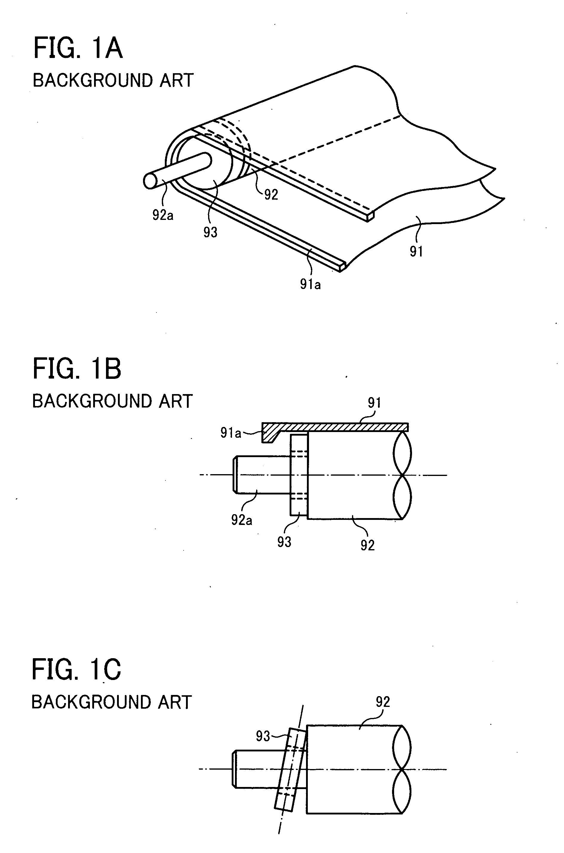
One problem associated with a multi-roller, fuser belt assembly depicted above is lateral misalignment or displacement of the fuser belt from its desired path of movement.
The problem occurs where the fuser belt rotating around the multiple support rollers slips laterally in an axial direction parallel to longitudinal, rotational axes of the belt supporting rollers, and ultimately climbs sideways over the outer circumference of the support roller to a position deviating from the original path of movement around the multiple support rollers.
Lateral displacement of the fuser belt, if not corrected, would result in various operational failures, such as imaging defects and belt breakage, due to improper positioning of the fuser belt relative to the belt supporting roller.
Such problem is particularly pronounced in high-speed, power-efficient applications where the belt support roller is formed of silicone rubber for obtaining a reduced thermal capacity, or is dimensioned to have a smaller diameter for accommodating an increased circumferential speed.
Although advantageous for their intended purposes, the belt tracking techniques described above would not function properly, where the belt rib interferes with the end face of the belt supporting roller to cause undue load on the rotating belt and rollers, resulting in destabilized rotation of the endless belt, and therefore aggravated belt tendency to climb over the roller circumference.
Unfortunately, however, this is not the case with high speed applications where the belt supporting roller is relatively large in diameter.
Recent trends in printing systems toward higher processing speed involve accelerating rotational speed of the multi-roller belt assembly with a corresponding increase in the diameter of the belt supporting roller, which makes it even more difficult to provide a reliable belt tracking mechanism with high immunity against belt failure due to lateral displacement of an endless looped belt.

Method used


Image

  • Endless belt assembly, fixing device, and image forming apparatus employing same
  • Endless belt assembly, fixing device, and image forming apparatus employing same
  • Endless belt assembly, fixing device, and image forming apparatus employing same

Examples


experiment iii

[0124]conducted to investigate the effects of lubrication of the interfacing surfaces 11a and 21a of the belt rib 11 and the roller flange 21 on susceptibility to failure upon lateral displacement of the fuser belt 10. In the experiments, immunity against belt failure was measured in terms of a lateral displacement speed Vf at which the rotating fuser belt 10 experiences failure as it slips laterally in the axial direction toward the longitudinal end of the heat roller 20, as is the case with Experiments I and II.

[0125]In Experiment III, the failure-inducing belt displacement speed Vf was measured as the belt rib 11, formed of silicone rubber, and the annular flange 21, formed of PI, were lubricated to vary the coefficient of kinetic friction therebetween at a PV factor of 500 kgf / cm2*m / min, so as to obtain a relation between the failure-inducing displacement speed Vf of the fuser belt 10 and the kinetic frictional coefficient of the belt rib 11 on the roller flange 21

[0126]FIG. 10 ...


PUM


Abstract

An endless belt assembly includes one or more rollers, an endless belt, and a belt tracking mechanism. The one or more rollers are disposed parallel to each other, each being rotatable around a rotational axis thereof. The endless belt is looped for rotation around the rollers. The belt tracking mechanism is disposed on at least one side of the endless belt assembly to prevent lateral displacement of the endless belt during rotation. The belt tracking mechanism includes an annular recess, an annular flange, and a circumferential rib. The annular recess is perimetrically formed on a longitudinal end face of the roller. The annular flange is disposed in the annular recess to rotate freely with respect to the roller. The circumferential rib extends along a side edge of an interior circumferential surface of the endless belt to contact the annular flange upon lateral movement of the belt.

Description

CROSS-REFERENCE TO RELATED APPLICATIONS[0001]The present patent application claims priority pursuant to 35 U. S. C. §119 from Japanese Patent Application No. 2010-168153, filed on Jul. 27, 2010, which is hereby incorporated by reference herein in its entirety.BACKGROUND OF THE INVENTION[0002]1. Field of the Invention[0003]The present invention relates to an endless belt assembly, a fixing device, and an image forming apparatus employing the same, and more particularly, to an endless belt assembly including an endless looped belt entrained around multiple rollers applicable to a fixing device that fixes a toner image in place on a recording medium with heat and pressure, and an electrophotographic image forming apparatus, such as a photocopier, facsimile machine, printer, plotter, or multifunctional machine incorporating several of those imaging functions, employing such an endless belt assembly.[0004]2. Description of the Background Art[0005]In electrophotographic image forming appa...

Claims


Application Information

Patent Timeline
Patent Type & Authority Applications(United States)
IPC IPC(8): G03G15/20
CPCG03G15/2053G03G2215/00143G03G2215/2032G03G2215/2025G03G2215/00151
Inventor TSUKIOKA, YASUTADA
Owner RICOH KK
Learn More