
Intravascular ventricular assist device

a technology of ventricular assist device and ventricular assist device, which is applied in the direction of wind motor components, non-positive displacement fluid engines, liquid fuel engine components, etc., can solve the problems of red blood cell rupture, ventricular assist device presents a daunting engineering challenge, and the heart lacks sufficient pumping capacity to meet the needs of the body, and achieves a greater aggregate cross-sectional area

Active Publication Date: 2012-02-02
HEARTWARE INC
View PDF2 Cites 78 Cited by
  • Summary
  • Abstract
  • Description
  • Claims
  • Application Information

AI Technical Summary

Benefits of technology

The invention is an implantable blood pump that can be used to assist the heart in pumping blood. The pump includes a housing with a rotating magnetic field, and stators surrounding the housing to induce rotation of the rotors. The rotors are suspended within the housing by magnetic and hydrodynamic forces. The pump can impel blood at a rate of 1-3 liters per minute. It can be positioned within an artery and is designed to maintain blood pressure within a range of 70-120 mm Hg. The pump is small in size, with a maximum lateral dimension of about 20 mm. The invention also includes methods of using the pump to provide cardiac assistance to a mammalian subject. The rotor bodies have helical channels that create continuous flow paths between the upstream and downstream ends of the rotor. The support surfaces of the rotor body have a radially outward extent that increases in a radially outward direction away from the rotor axis. These surfaces define hydrodynamic bearing surfaces.

Problems solved by technology

In certain disease states, the heart lacks sufficient pumping capacity to meet the needs of the body.
Design of a ventricular assist device presents a daunting engineering challenge.
Severe mechanical action can lead to hemolysis, or rupture of the red blood cells, with serious consequences to the patient.
Also, blood in contact with an artificial surface, such as the surfaces of a pump, tends to clot.
Balloon assist devices of this nature have numerous limitations including limited durability and limited capacity.
However, implantation of such a pump involves a majorly invasive surgical procedure.
These complex systems are susceptible to failure.

Method used


Image

  • Intravascular ventricular assist device
  • Intravascular ventricular assist device
  • Intravascular ventricular assist device

Examples


Embodiment Construction

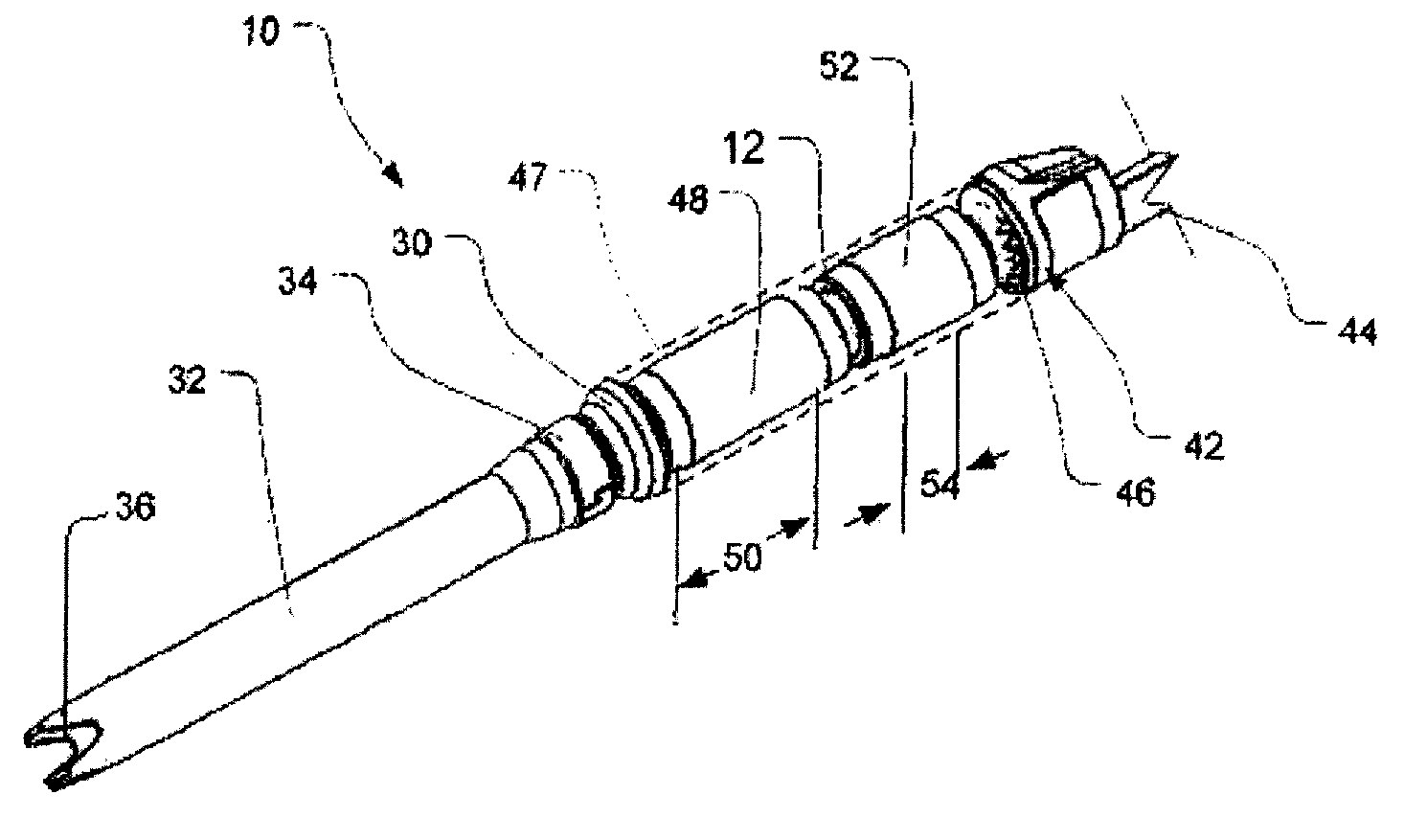
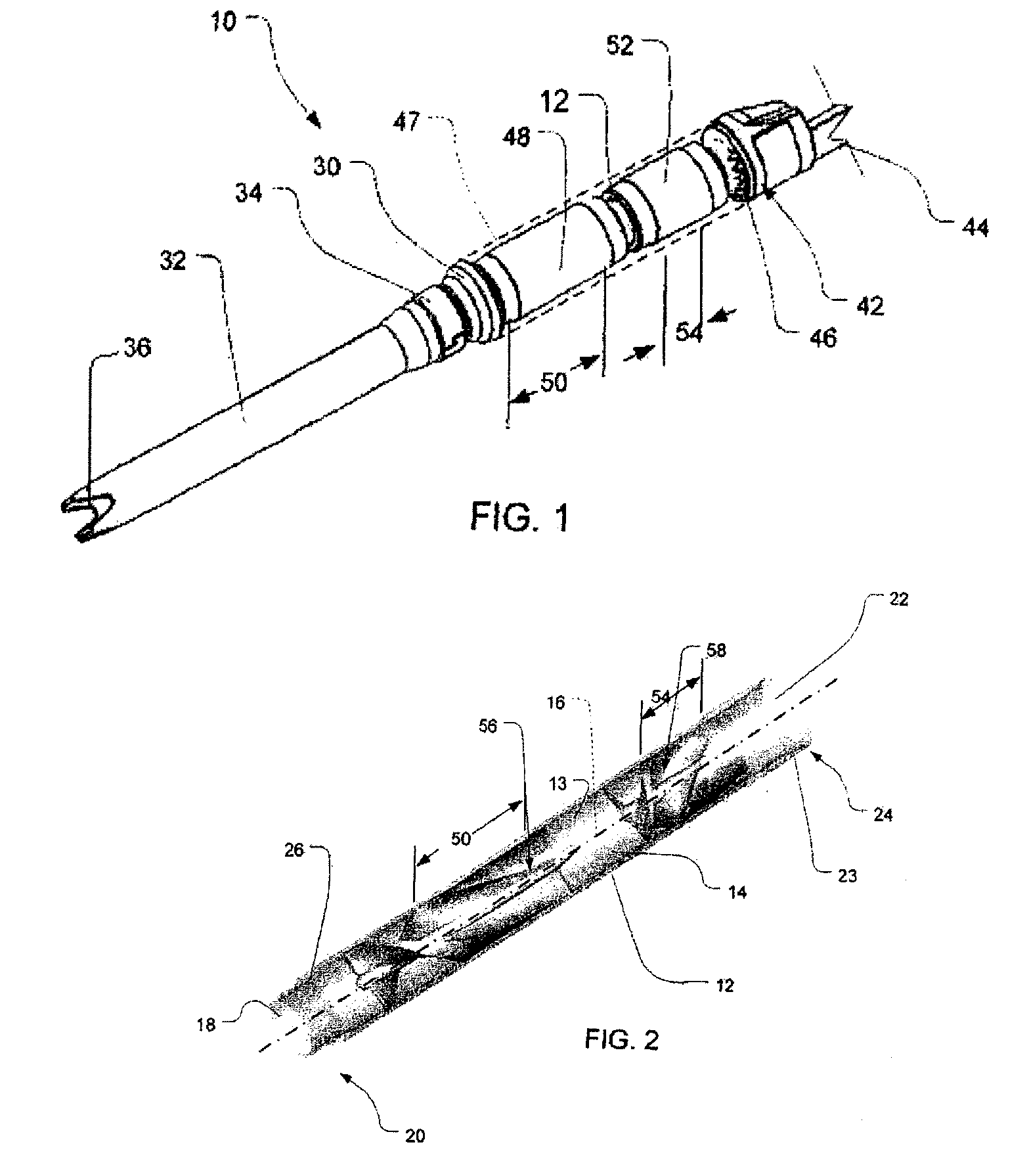
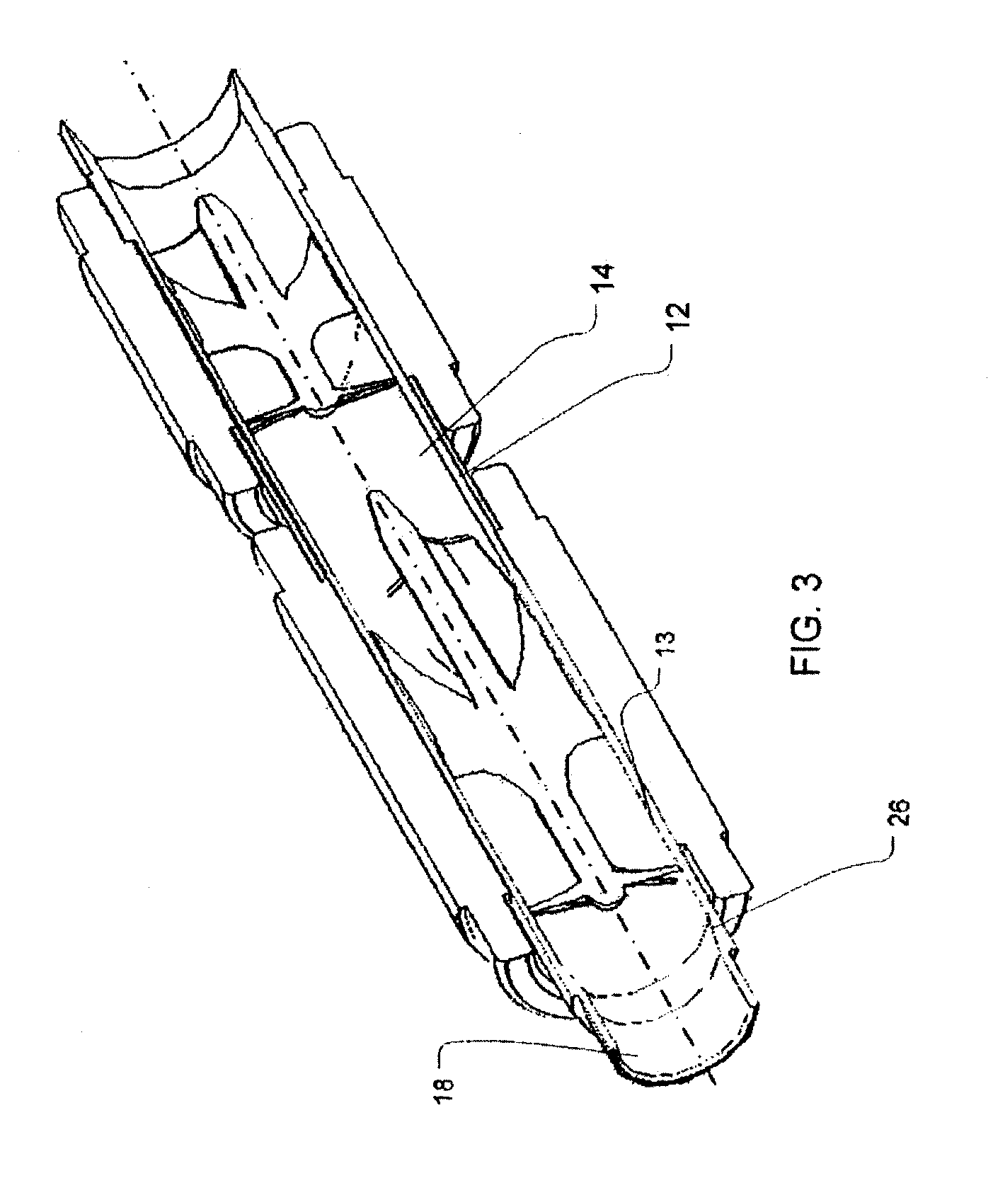
[0032]A pump 10 in accordance with one embodiment of the invention includes a housing 12 (FIGS. 1, 2 and 3). Housing 12 is a ceramic tube defining a central bore 14 having an axis 16. Bore 14 is cylindrical and has a constant diameter over the major portion of its length. The interior surface 13 of the housing defining bore 14 is smooth, and desirably has a surface roughness on the order of 4 micro inches rms or less. Merely by way of example, the inside diameter of bore 14 in this constant diameter region may be about 0.178 inches (“in”), and the wall thickness of the housing may be about 0.010 in. Housing 12 defines an inlet 18 at an end 20 of the housing, referred to herein as the inlet or upstream end, and an outlet 22 communicating with bore 14 at an output or downstream end 24 of the housing. The inside diameter of inlet 18 is slightly less than the inside diameter of bore 14. The housing includes an inlet transition section 26 having an inside diameter which increases progres...


PUM


Abstract

One aspect of an intravascular ventricular assist device is an implantable blood pump where the pump includes a housing defining a bore having an axis, one or more rotors disposed within the bore, each rotor including a plurality of magnetic poles, and one or more stators surrounding the bore for providing a magnetic field within the bore to induce rotation of each of the one or more rotors. Another aspect of the invention includes methods of providing cardiac assistance to a mammalian subject as, for example, a human. Further aspects of the invention include rotor bodies having helical channels formed longitudinally along the length of the body of the rotor where each helical channel is formed between peripheral support surface areas facing radially outwardly and extending generally in circumferential directions around the rotational axis of the rotor.

Description

[0001]This application is a divisional application of U.S. Ser. No. 12 / 072,471, filed Feb. 26, 2008, which claims the benefit of U.S. Provisional Application No. 60 / 903,781, filed Feb. 26, 2007, the contents of all of which are incorporated by reference in their entirety into this application.BACKGROUND OF THE INVENTION[0002]The present invention relates to pumps usable as implantable ventricular assist devices, to components useful in such pumps, and to methods of using the same.[0003]In certain disease states, the heart lacks sufficient pumping capacity to meet the needs of the body. This inadequacy can be alleviated by providing a mechanical pump referred to as a ventricular assist device to supplement the pumping action of the heart. It would be desirable to provide a ventricular assist device which can be implanted and which can remain in operation for months or years to keep the patient alive while the heart heals, or which can remain in operation permanently during the patien...

Claims


Application Information

Patent Timeline
Patent Type & Authority Applications(United States)
IPC IPC(8): A61M1/10F04D29/38A61M60/135A61M60/174A61M60/237A61M60/422A61M60/538A61M60/806A61M60/81A61M60/824A61M60/857A61M60/861A61M60/873A61M60/876A61M60/878
CPCA61M1/101A61M1/125A61M1/122A61M60/824A61M60/422A61M60/135A61M60/81A61M60/878A61M60/806A61M60/237A61M60/538A61M60/861A61M60/873A61M60/876A61M60/13A61M60/148A61M60/419A61M60/174A61M2205/0211A61M2205/0272A61M2205/8206A61M2210/127
Inventor LAROSE, JEFFREY A.SHAMBAUGH, JR., CHARLES R.WHITE, DANIEL G.MARQUIS, RICHARD A.WHITE, STEVEN A.TRICHI, KARTIKEYANTHYAGARAJAN, PALANIVELU
Owner HEARTWARE INC
Learn More