
Multi-junction photovoltaic cell with nanowires

a photovoltaic cell and nanowire technology, applied in the field of photovoltaic cells, can solve the problems of limiting the conversion efficiency of light into electricity, the efficiency of the dot junction solar cell is still not optimal, and the disadvantage of the dot junction solar cell in terms of photon energy efficiency, so as to improve the efficiency of the dot junction solar cell and efficiently convert light into electricity

Inactive Publication Date: 2012-02-09
SOL VOLTAICS
View PDF3 Cites 12 Cited by
  • Summary
  • Abstract
  • Description
  • Claims
  • Application Information

AI Technical Summary

Benefits of technology

[0014]Moreover, since a nanowire is used for forming the second p-n junction additional advantages are achieved. These include, for example and in comparison with a traditional planar III-V multi-junction solar cell, a possibility to achieve higher efficiency values since it is more easy to arrange more p-n junction elements in a nanowire, a reduced need of perfect lattice matching over large substrate areas for purpose of avoiding dislocations, and an improved functionality since it is more easy to obtain a high degree of compositional homogeneity.
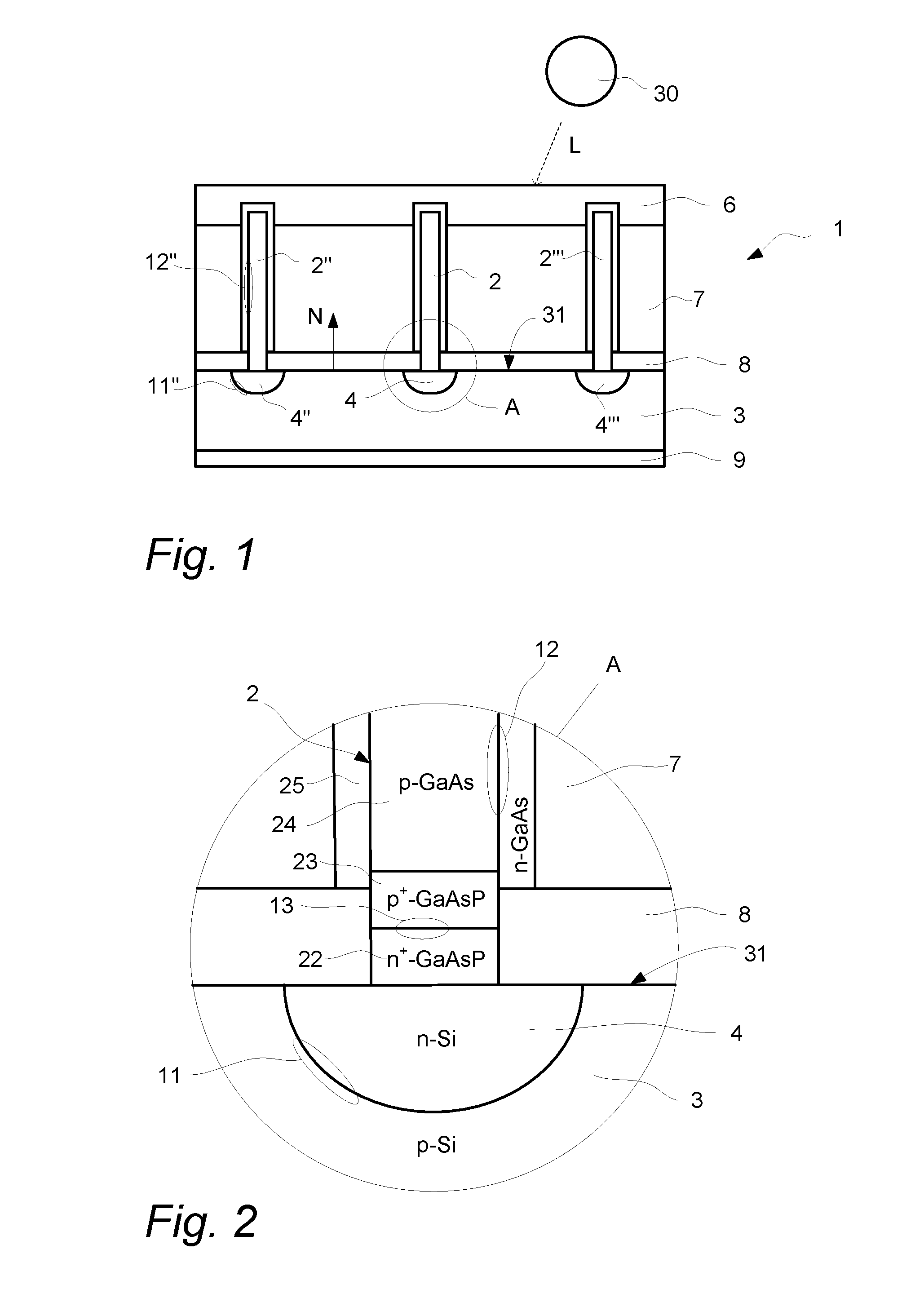
[0026]The multi-junction photovoltaic cell may be configured to be arranged with the surface of the substrate facing a source of light. This means that the doped region of the surface, i.e. the point-contact diode, is arranged on the side of the substrate that is intended to face the light when the photovoltaic cell is in operation. This is different from many known point-contact solar cells and results in an efficient collaboration between the first and second p-n junctions when it comes to efficiently using the energy of the sun for producing electricity.

Problems solved by technology

One factor that limits the conversion efficiency from light to electricity is reverse current leakage across the p-n junction.
However, even if reverse current leakage is limited, the efficiency of the dot-junction cell is still not optimal.
For example, since each dot-junction is a single band gap solar cell, efficiency is limited due to the inability to efficiently convert the broad range of energy that photons possess in the solar spectrum.
Accordingly, even if a dot-junction photovoltaic cell is advantageous with respect to a reduced reverse current leakage, a dot junction solar cell still has a disadvantage in terms of photon energy efficiency, i.e. a large portion of the solar spectrum is lost to heat and not converted into electricity.

Method used


Image

  • Multi-junction photovoltaic cell with nanowires
  • Multi-junction photovoltaic cell with nanowires
  • Multi-junction photovoltaic cell with nanowires

Examples


Embodiment Construction

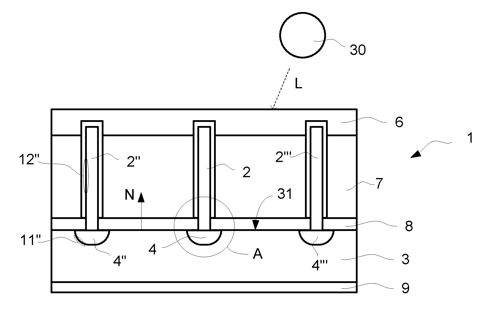
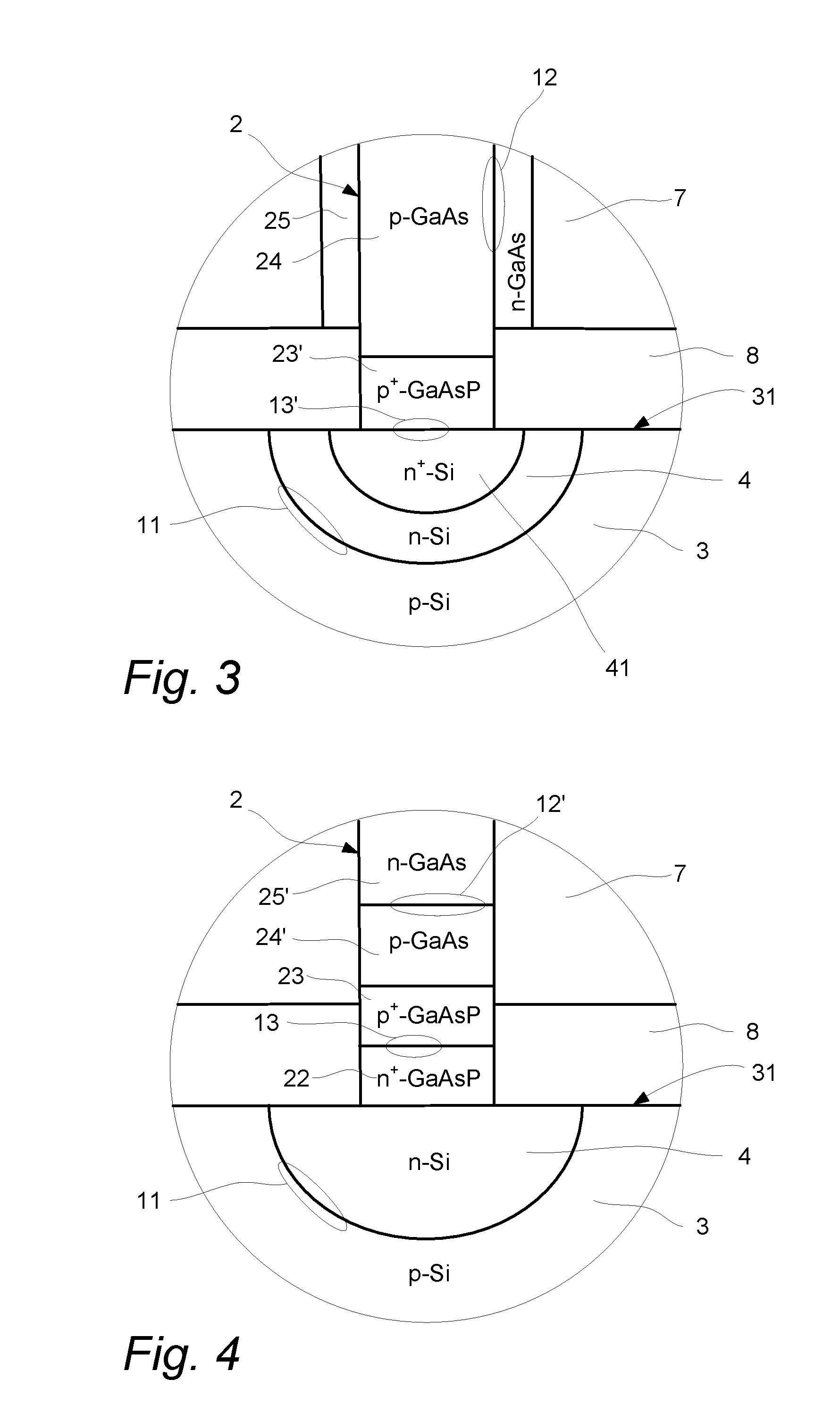
[0036]With reference to FIG. 1 a multi-junction photovoltaic (solar) cell 1 comprises a planar substrate 3 made of p-doped Si (silicon). The substrate 3 has an upper surface 31 intended to face light L that is incident on the solar cell 1, i.e. the upper surface 31 is the upper, front side of the substrate 3. A planar back contact 9 made of e.g. Al (aluminum) is arranged on the lower surface of the substrate 3 opposite the upper surface 31. In the upper surface 31 of the substrate 3 an n-doped region 4 is located. This region 4 is dome-shaped with the planar part of the region 4 being aligned with a plane formed by the upper surface 31. Accordingly, the curved part of the dome shaped region 4 extends into the substrate 3. However, the extent of the region 4 is smaller than the total thickness of the substrate 3. A nanowire 2 is located on the substrate 3 at the center position of the doped region 4. This means that a geometrical axis defined by the longitudinal direction of the nano...


PUM


Abstract

A multi junction photovoltaic cell for converting light into electrical energy, comprising a substrate (3) having a surface (31), wherein a region (4) at the surface (31) of the substrate (3) is doped such that a first p-n junction is formed in the substrate (3). The photovoltaic cell has a nanowire (2) that is arranged on the surface (31) of the substrate (3) at a position where the doped region (4) is located in the substrate (3), such that a second p-n junction is formed at the nanowire (2) and in series connection with the first p-n junction.

Description

TECHNICAL FIELD[0001]The invention relates to a photovoltaic cell that includes a nanowire as an active component.BACKGROUND ART[0002]The interest in solar cell technology has increased over the last years as energy prices steadily reach higher levels and as the drawbacks of using fossil fuel becomes more and more obvious. Moreover, technology breakthroughs imply that large scale production of high efficiency photovoltaic (solar) cells is possible.[0003]For example, rectifying junctions, such as p-n junctions and Schottky diodes, are fabricated in semiconducting materials to make photovoltaic cells that are used in solar cell devices as well as in photodetectors. A photovoltaic cell converts light into electricity as light illuminates the p-n junction and creates pairs of oppositely charged particles: electrons and holes. These charges are separated by the rectifying junction to produce an electrical current. Photodetectors work on a similar principle.[0004]Conventional photovoltaic...

Claims


Application Information

Patent Timeline
IPC IPC(8): H01L31/0352B82Y15/00H01L31/078
CPCH01L31/03529H01L31/061H01L31/0687H01L31/0693H01L31/0725Y10S977/954Y02E10/544H01L31/0475Y10S977/948Y10S977/762H01L27/1422H01L31/078H01L31/0352
Inventor OLSON, JERRY M.
Owner SOL VOLTAICS
Learn More