LED unit

Active Publication Date: 2012-02-09
PANASONIC INDAL DEVICES SUNX
View PDF5 Cites 12 Cited by
  • Summary
  • Abstract
  • Description
  • Claims
  • Application Information

AI Technical Summary

Benefits of technology

[0018]It is preferred that each the LED module has a fourth surface which is configured to pass the light emitted from the LED chip. A plurality of the LED modules are arranged along a direction of a short side of the fourth surface. This configuration makes it possible to increase the intensity of the light emitted from the LED unit 1.
[0019]It is preferred that the LED module is connected to the first surface of the heat radiation plate with braze or the adhesive agent having the heat conductivity. This configuration makes it possible to omit the screw hole from the LED module. In addition, this configuration makes it possible to connect the LED module to the heat radiation plate while keeping high heat conductivity. Furthermore, it is possible to downsize the LED module. Therefore, it is possible to mount the LED module with high-density packaging.
[0020]Furthermore, it is preferred that

Problems solved by technology

This results in the increase of the manufacturing cost.
In addition, when manufacturing the LED module,

Method used


Image

  • LED unit
  • LED unit
  • LED unit

Examples


first embodiment

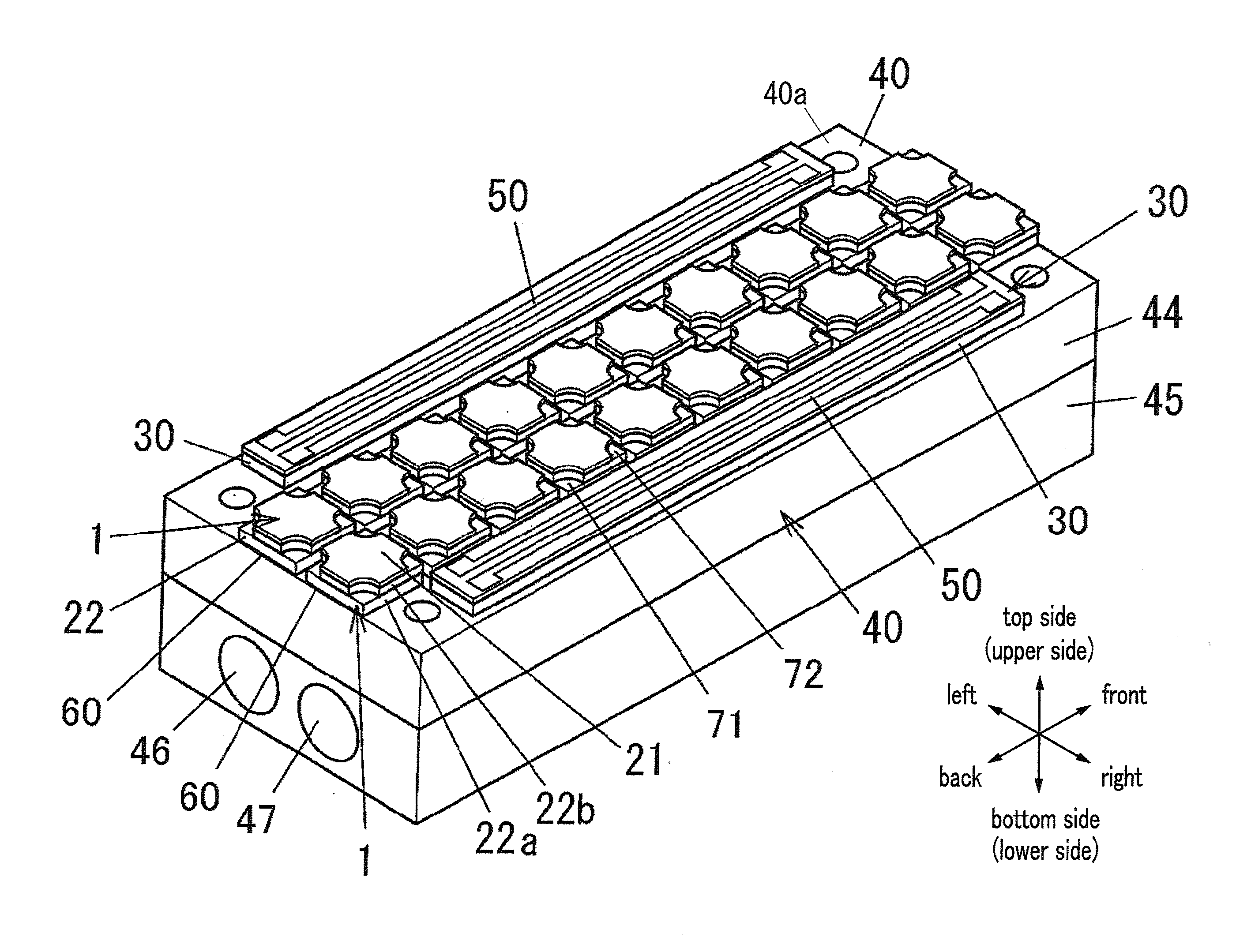
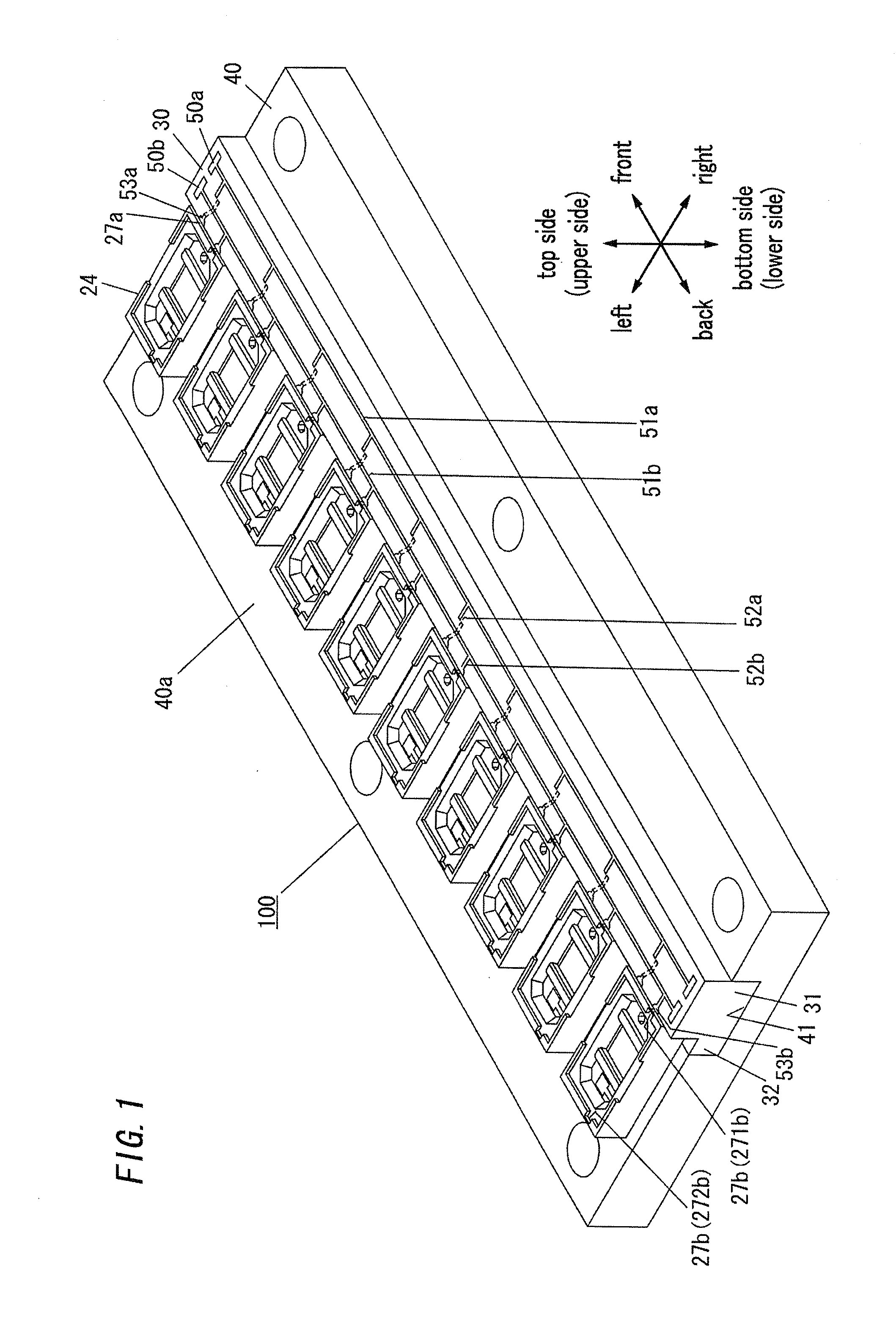
[0043]The first embodiment discloses the LED unit 100; the LED unit 100 comprises a plurality of the LED modules 1, an electrical insulator 30, and a heat radiation plate 40 shown in FIG. 1; the LED module 1 has an approximately cuboid; the electrical insulator 30 has an approximately cuboid; the heat radiation plate 40 has an approximately cuboid. The electrical insulator 30 is provided at its first surface with a wiring line (patterned circuit) 50 which is formed to establish the electrical connection of a plurality of the LED modules 1 with each other. (In this embodiment, the first surface of the electrical insulator 30 is defined by a top surface of the electrical insulator 30.) The wiring line 50 comprises a wiring line 50a of negative side and a wiring line 50b of positive side. Hereinafter, explanations of the direction indicated in FIG. 1 are made. The upper-lower direction is defined by the thickness direction of the heat radiation plate 40. Each one of the LED module 1 is...

second embodiment

[0070]FIG. 5 shows the LED unit 100 of this embodiment. The LED unit 100 of this embodiment has basic components which are approximately in common with the basic components of the first embodiment. Therefore, the components in common with the components in the first embodiment are symbolized by the same reference numerals, whereby the explanation is omitted. In this embodiment, the number of the grooves 41 of the heat radiation plate 40, he number of the electrical insulator 30, and the connection portion by means of the solder are different from the first embodiment.

[0071]In this embodiment, the heat radiation plate 40 is provided at its top surface with two grooves. The heat radiation plate 40 is provided at its top surface 40a with two electrical insulators 30 (30a, 30b) which are disposed within the two grooves 41, respectively, formed on the top surface 40a. The two electrical insulator 30a, 30b are mounted on the left side of the top surface of the heat radiation plate 40 and ...

third embodiment

[0076]FIG. 7 shows the LED unit 100 of this embodiment, the LED unit 100 of this embodiment has the basic components which are approximately equivalent to the basic component of the first embodiment. Therefore, the components in common with the components of the first embodiment are symbolized by the same reference numerals, whereby their explanations are omitted. The configuration of each the LED module 1 in this embodiment is approximately in common with the first embodiment. This embodiment is different from the first embodiment in the technical feature that the LED modules 1 are connected in series. FIG. 8 A shows the circuit diagram which indicates the connection relationship of the LED chip 10 and the terminals 27a, 27b of the LED unit in this embodiment.

[0077]In this embodiment, the patterned circuit 50 is formed to connect a plurality of the LED modules 1 in series, and is provided with pads 53a, 53b, which are connected to each the negative terminal 27a and the positive ter...


PUM


Abstract

The LED unit 100 comprises a plurality of the LED module 1 and the heat radiation plate. Each the LED module 1 comprises the LED chip and the package for incorporating the LED chip therein; the package has the electrical insulation property. Each the package comprises the sub-mount member which is located between the LED chip and the heat radiation plate and which has heat conductivity; these are integrally formed. The LED modules are arranged on the first surface of the heat radiation plate. This configuration makes it possible for the LED unit to efficiently disperse the heat in the LED chip 10 to the heat radiation plate.

Description

TECHNICAL FIELD[0001]This invention relates to an LED unit which comprises a plurality of LED modules.BACKGROUND ART[0002]Conventionally, the discharge lamp and the laser oscillator are used as a light source, and the lighting device with the light source is produced. Recently, in order to achieve the low consumption of the electrical power and to improve the operating time of the lighting device, the LED unit with the LED modules (light emitting diode module) is produced instead of the discharge lamp.[0003]The LED module comprises an LED chip and a package which houses the LED chip. The LED modules used to be combined with each other to produce light having an amount same as an amount of the prior lighting device such as discharge lamp. Japanese patent application publication No. 2004-528698A discloses the LED module which comprises a plurality of the LEDs. The LED module comprises the LEDs each of which are disposed on the sub-mount member having an electrical insulation property;...

Claims


Application Information

Patent Timeline
IPC IPC(8): H01L33/62
CPCF21K9/00F21V29/83H01L33/62H01L33/642H01L33/648H05K1/0203H05K1/117H05K3/0061H05K2201/09745H05K2201/10106H05K2201/10446F21V19/0015F21V19/045H01L2924/0002H01L33/486F21V29/58F21V29/002F21V29/004H01L2924/00F21V19/04F21V29/70
Inventor URANO, YOUJI
Owner PANASONIC INDAL DEVICES SUNX
Why Eureka
Try Eureka