Digital Phase Lock System with Dithering Pulse-Width-Modulation Controller

a phase lock and controller technology, applied in pulse generators, pulse manipulation, pulse techniques, etc., can solve the problems of increased jitter, finite phase error amplification, and end-phase error amplification

Active Publication Date: 2012-02-09
HONG KONG APPLIED SCI & TECH RES INST
View PDF1 Cites 42 Cited by
  • Summary
  • Abstract
  • Description
  • Claims
  • Application Information

AI Technical Summary

Problems solved by technology

However, digital phase-lock systems have a quantization error that results in a finite phase error.
However, this finite phase error is amplified by the feedback divider and applied to the phase comparator.
The loose phase tracking with the input clock ultimately results in increased jitter in the form of a large close-in phase noise.
However, this phase noise is much lower for large frequency offsets.
However, the DSM produces a larger far-away phase error, as can be seen at the higher frequencies in FIG. 2.
Jitter may be too high when higher frequencies are used.
Another problem with the DSM is that the DSM is operated at a high frequency, and has high power consumption at these high frequencies.

Method used


Image

  • Digital Phase Lock System with Dithering Pulse-Width-Modulation Controller
  • Digital Phase Lock System with Dithering Pulse-Width-Modulation Controller
  • Digital Phase Lock System with Dithering Pulse-Width-Modulation Controller

Examples


Embodiment Construction

[0024]The present invention relates to an improvement in digital phase-lock systems. The following description is presented to enable one of ordinary skill in the art to make and use the invention as provided in the context of a particular application and its requirements. Various modifications to the preferred embodiment will be apparent to those with skill in the art, and the general principles defined herein may be applied to other embodiments. Therefore, the present invention is not intended to be limited to the particular embodiments shown and described, but is to be accorded the widest scope consistent with the principles and novel features herein disclosed.

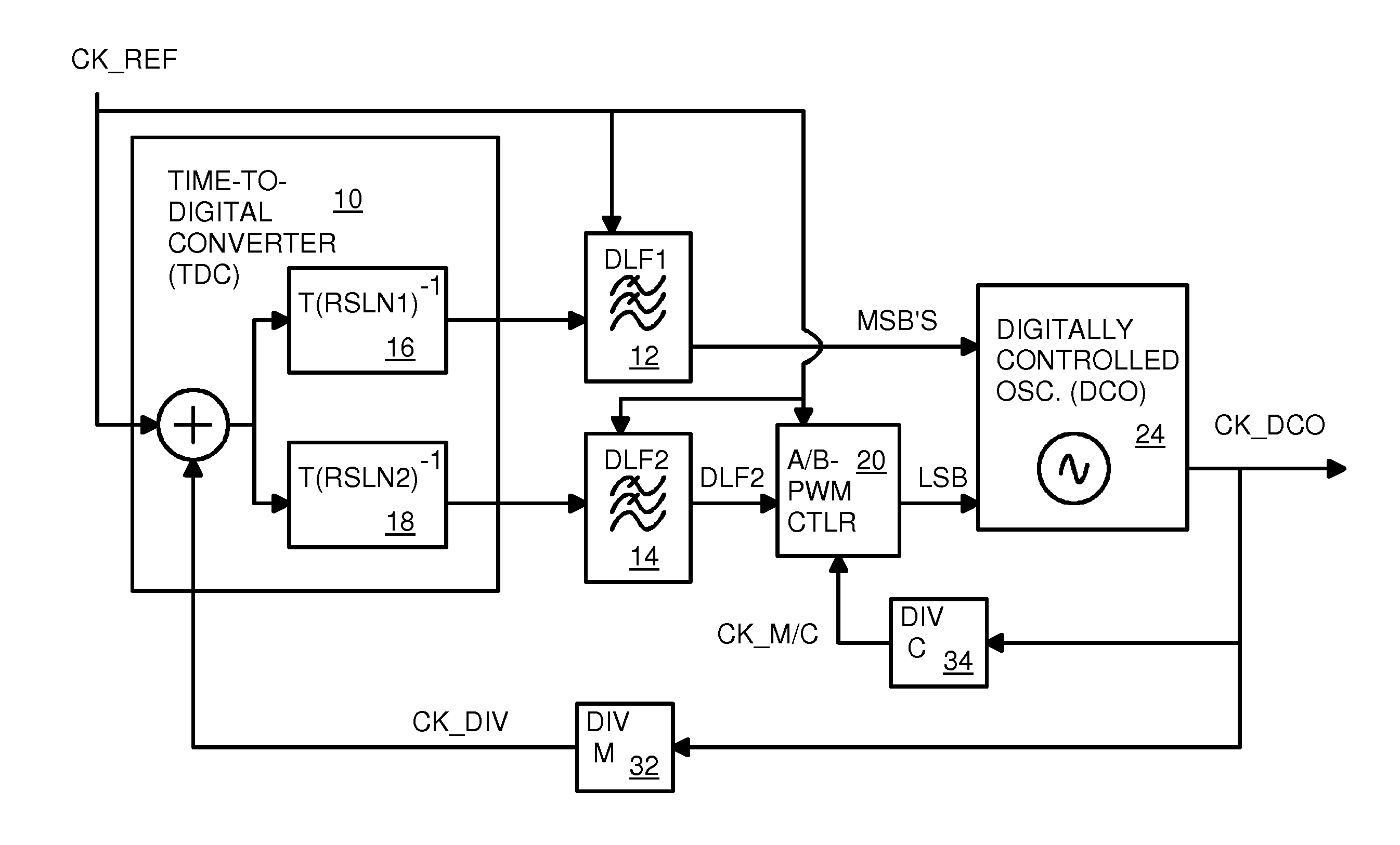
[0025]The inventors have discovered that a Pulse-Width-Modulation (PWM) control circuit can replace a delta-sigma modulator (DSM) and still reduce close-in phase noise. Far-away phase noise is not significantly increased with the PWM control as was the case with the DSM. Many parts of the PWM control circuit can operate at ...


PUM


Abstract

A Digital Phase-Locked Loop (DPLL) has a digitally-controlled oscillator (DCO) that generates an output clock frequency determined by a digital input with most-significant-bits (MSB's) and a least-significant-bit (LSB). The LSB is generated by a Pulse-Width-Modulation (PWM) controller clocked by a control clock that is the output clock divided by C. A reference clock is compared to a feedback clock that is the output clock divided by M. The PWM controller generates M/C LSB's for each reference clock period and loads them in parallel to a parallel-to-serial shift register that serially delivers the LSBs. The pulse width is determined by a fine digital loop filter that filters phase comparison results using a fine time resolution. A coarse digital loop filter generates the MSB's from phase comparison results using a coarse time resolution. LSB waveforms are dithered by randomly selecting high-going or low-going pulses and randomly adjusting pulse widths.

Description

FIELD OF THE INVENTION[0001]This invention relates to digital Phase-locked loops (PLL's), and more particularly to digital phase-locking systems using pulse-width modulation (PWM) control.BACKGROUND OF THE INVENTION[0002]Phase-locked loops (PLL's) are widely used for generating clocks for a variety of systems. More recently, analog PLL's have been replaced by digital PLLs. Digital controls in such digital PLLs' may be less susceptible to noise while consuming less power.[0003]However, digital phase-lock systems have a quantization error that results in a finite phase error. This quantization error is not preset in analog systems. The finite phase error produced by the digital oscillator appears on the output clock. However, this finite phase error is amplified by the feedback divider and applied to the phase comparator. The loose phase tracking with the input clock ultimately results in increased jitter in the form of a large close-in phase noise.[0004]FIG. 1 is a graph of estimated...

Claims


Application Information

Patent Timeline
Patent Type & Authority Applications(United States)
IPC IPC(8): H03L7/08
CPCH03L7/093H03L2207/50H03L2207/06
Inventor CHAN, CHI FATLIN, CHIEN-WEICHUNG, GORDON
Owner HONG KONG APPLIED SCI & TECH RES INST
Why Eureka
Try Eureka