High-resolution ranging and location finding using multicarrier signals

a multi-carrier signal, high-resolution technology, applied in the direction of frequency-division multiplex, data switching network, instruments, etc., can solve the problem of indoor reception of gps signals, limited accuracy of receiver timing offset, and typically not synchronized in time with sufficient accuracy

Inactive Publication Date: 2012-02-09
AMERISYS INC
View PDF5 Cites 224 Cited by
  • Summary
  • Abstract
  • Description
  • Claims
  • Application Information

AI Technical Summary

Problems solved by technology

Drawbacks of this approach include the need to incorporate a GPS receiver in wireless devices, potential problems with the reception of GPS signals indoors and in the vicinity of tall buildings or in mountainous regions where signal blockage and multipath interference would Occur.
One difficulty in using the time-of-flight approach in wireless digital communication systems is the limited accuracy of a receiver timing offset, also referred to in the art as the receiver clock offset, relative to the transmitted signal clock.
Although Tx-clock and Rx-clock may be suitably well synchronized in frequency, they are typically not synchronized in time with sufficient accuracy.
However, an external reference clock may not always be available or practical.
Although methods of estimating the receiver timing offset in the absence of a reference clock are known in the art, such as by correlating a section of the received signal having a known modulation pattern with a copy of the modulation pattern saved at the receiver, these methods often have limited accuracy.
In particular, most known methods of estimating the receiver timing offset are limited in accuracy by a sampling time period Ts used in digitizing the received signal, so that the timing offset estimation accuracy is on the order of ±Ts / 2, which may not be enough to provide a required ranging accuracy.
One disadvantage of this method, however, is the large number of additional measurements that the receiver has to perform in this method, with the proportionally increased computation requirements, so that the method does not scale well if the required increase in the timing offset accuracy is, for example, 10-fold or 100-fold.

Method used


Image

  • High-resolution ranging and location finding using multicarrier signals
  • High-resolution ranging and location finding using multicarrier signals
  • High-resolution ranging and location finding using multicarrier signals

Examples


Embodiment Construction

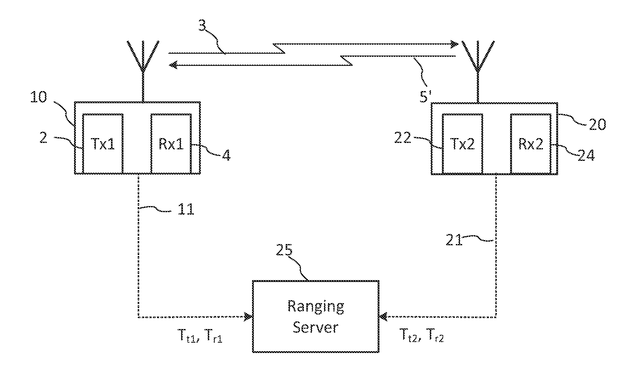
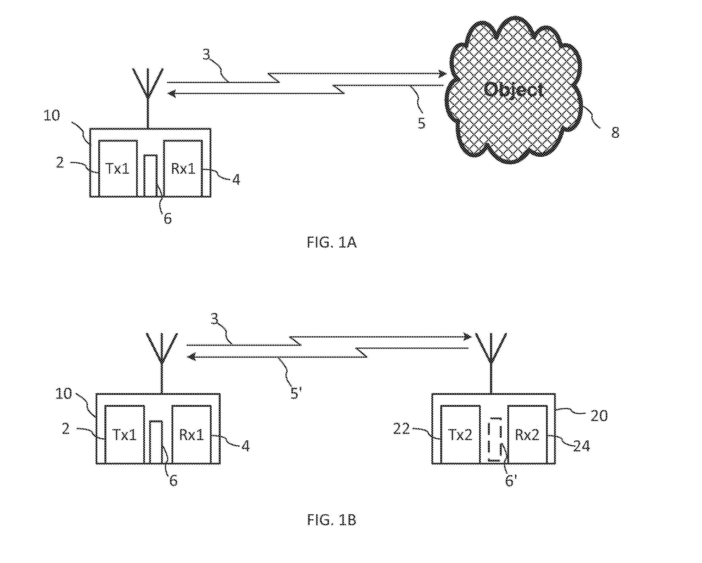
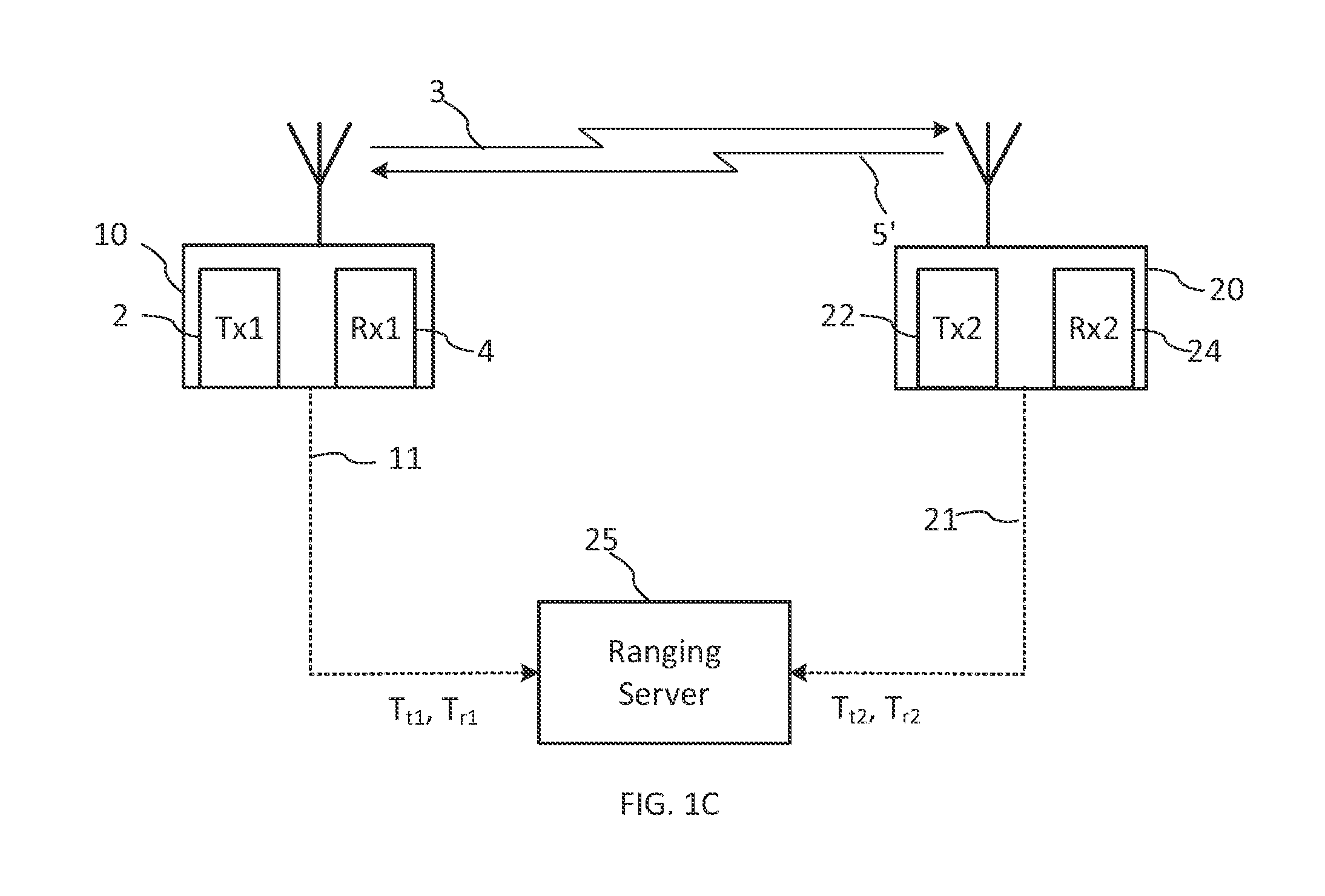
[0044]In the following description, reference is made to the accompanying drawings which form a part thereof and which illustrate several embodiments of the present invention. It is understood that other embodiments may be utilized and structural and operational changes may be made without departing from the scope of the present invention. The drawings include flowcharts and block diagrams. The functions of the various elements shown in the drawings may be provided through the use of analog RF circuitry and data processing hardware such as but not limited to dedicated logical circuits within a data processing device, as well as data processing hardware capable of executing software in association with appropriate software. When provided by a processor, the functions may be provided by a single dedicated processor, by a single shared processor, or by a plurality of individual processors, some of which may be shared. The term “processor” should not be construed to refer exclusively to...


PUM


Abstract

The invention relates to methods and systems for accurate ranging and geo-locationing using coherent multicarrier (CM) signals and based on a high-resolution estimation of a receiver timing offset in a signal receiver that receives ranging CM signals. A transmitter transmits a ranging CM signal having a known subcarrier modulation pattern. The receiver samples the ranging CM signal it receives reflected back from an object or from the remote transmitter, and processes the sampled signal that preserves relative subcarrier phases using a high-resolution model channel response function to determine the receiver timing offset with resolution much better than the receiver sampling period. The receiver timing offset is used to determine a flight time for the ranging CM signal with high accuracy.

Description

CROSS-REFERENCE TO RELATED APPLICATIONS[0001]The present invention claims priority from U.S. Provisional Patent Application No. 61 / 312,687 filed Mar. 11, 2010, which is incorporated herein by reference for all purposes. It is also a continuation-in-part of a U.S. patent application Ser. No. 11 / 868,190, entitled “System and Method to Range Using Multi-Carrier Phasing Synchronization”, filed Oct. 5, 2007, which claims priority from U.S. Provisional Patent Application No. 60 / 828,326 filed Oct. 5, 2006, all of which are incorporated herein by reference for all purposes.TECHNICAL FIELD[0002]The present invention generally relates to systems and devices that can use coherent multicarrier signals, and more particularly relates to methods and systems for receiver timing offset estimation, ranging and location finding using coherent multicarrier signals.BACKGROUND OF THE INVENTION[0003]Many wireless communication systems may benefit from, or even require, knowledge of geographical location o...

Claims


Application Information

Patent Timeline
Patent Type & Authority Applications(United States)
IPC IPC(8): G01S5/02H04L12/26
CPCG01S5/0289G01S11/02G01S5/0215G01S13/84G01S13/876G01S13/82
Inventor REEDE, IVANCHOUINARD, GERALD
Owner AMERISYS INC
Why Eureka
Try Eureka