Circuit and Method for Peak Detection with Hysteresis

a peak detection and hysteresis technology, applied in the field of communication systems, can solve the problems of system failure, inability to inability to accurately detect the peak amplitude of small input signals, etc., to achieve accurate hysteresis, accurate peak detection, and accurate hysteresis

Inactive Publication Date: 2012-02-09
NXP BV
View PDF4 Cites 17 Cited by
  • Summary
  • Abstract
  • Description
  • Claims
  • Application Information

AI Technical Summary

Benefits of technology

[0005]A system and method for peak detection with hysteresis is disclosed. The peak detection system comprises a high threshold path and a low threshold path, wherein both paths are coupled to an input signal to detect the instances of peak signal exceeding the high threshold and the instances of peak signal falling below the low threshold respectively. The high threshold path and the low threshold path each comprise a pre-amplifier and a peak detection circuit, where the gains of the pre-amplifiers can be adjusted and the reference voltages for the respective peak detection circuits can be adjusted. Since most peak detection circuits exhibit non-linear transfer characteristic, particularly at low signal level, amplifying the input signal will bring the signal level to a more linear region for accurate peak detection. In one embodiment of the peak detection with accurate hysteresis, the peak detectors for the high threshold path and the low threshold path have the same size and the same reference voltage is applied to both peak detectors.
[0006]The method for peak detection with accurate hysteresis comprises: providing a first gain factor for amplifying the input signal to obtain a first amplified sign...

Problems solved by technology

At the same time, the RF signal is usually small and susceptible to noises.
The detected peak amplitude may be affected by noises which may inadvertently cause the gain control to fluctuate randomly and frequently so as to cause the system to perform improper...

Method used


Image

  • Circuit and Method for Peak Detection with Hysteresis
  • Circuit and Method for Peak Detection with Hysteresis
  • Circuit and Method for Peak Detection with Hysteresis

Examples


Embodiment Construction

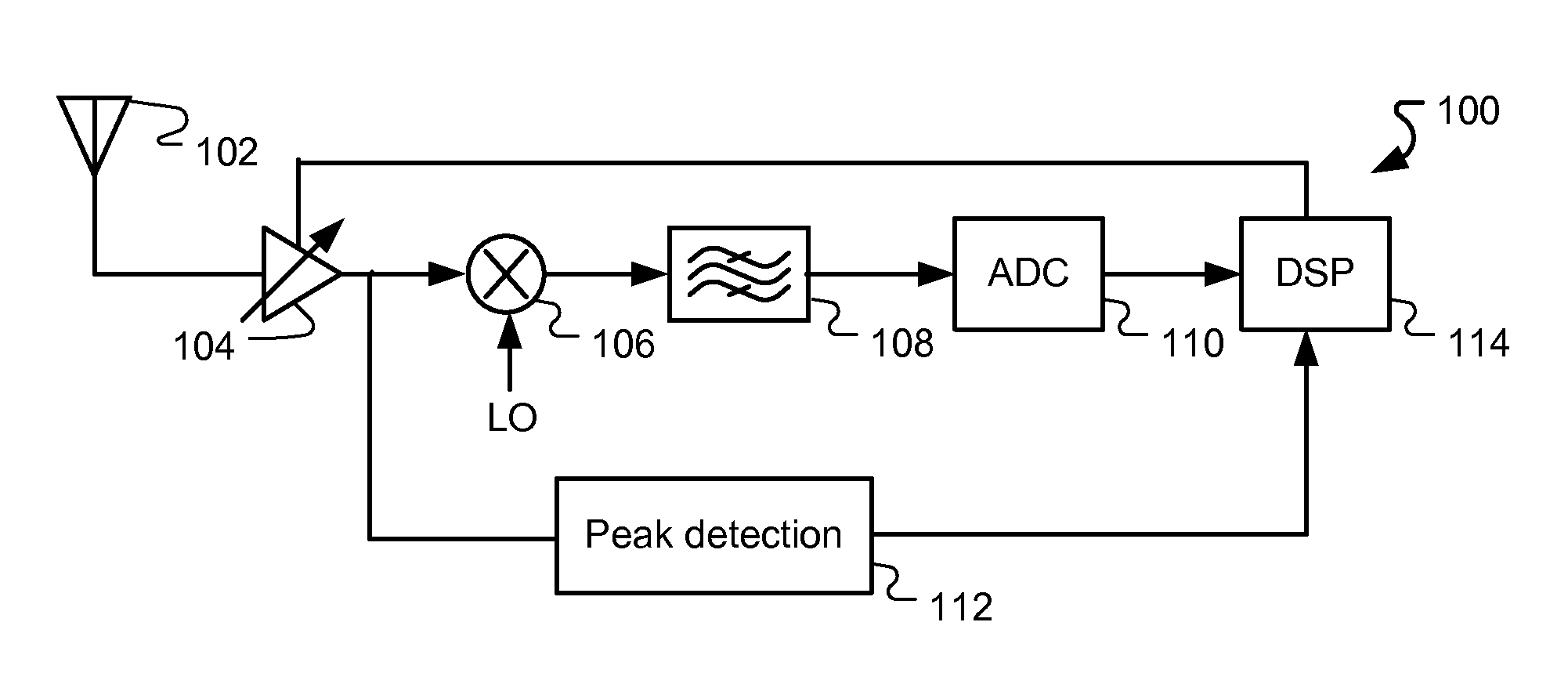
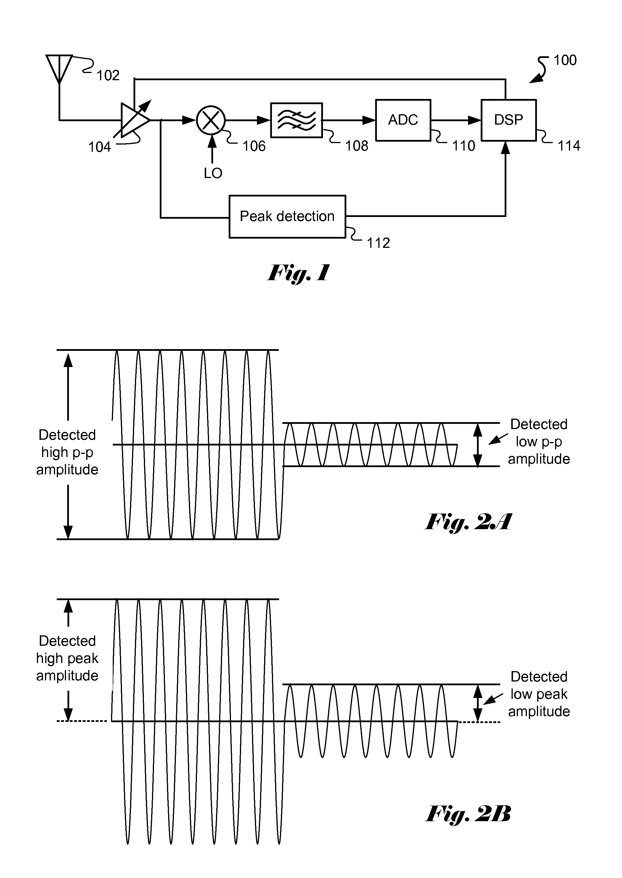
[0018]FIG. 1 illustrates a communication receiver 100 using an automatic gain control (AGC) to automatically adjust the gain of the front-end LNA in order to allow the receiver to be used with a wide dynamic input range. The AGC loop comprises peak detection 112 to detect the peak amplitude of the signal amplified by the LNA 104. The peak detection provides digital information related to the detected amplitude and one or more reference signal. The digital information, such as multiple bits to indicate whether the amplitude of input signal is above or below reference signals, is provided to a digital signal processing (DSP) module 114 so that the DSP may generate proper control signal for the LNA according to the digital information. The detected peak amplitude is used to control the LNA gain. In this particular example, the DSP module 114 is used to derive the necessary control signal for the LNA. The DSP module 114 is also used in the main receive path to perform other receiver tas...


PUM


Abstract

In a communication system, the signal received or transmitted is required to be maintained within a range for proper operation. For example, a radio frequency signal received from an antenna is usually amplified by a low-noise amplifier (LNA) with adjustable gain. The input RF signal is properly amplified by the LNA further processing by subsequently receive path of the receiver. A peak detector may be used to detect the peak amplitude of the amplified input and provides a proper gain for the LNA. The detected peak amplitude may be affected by the noises which may inadvertently cause the gain control to fluctuate randomly. In order to avoid the above issues, some hysteresis has to be built into the peak detection so that the gain control will not be so sensitive to the noise. The present invention discloses a system and method for peak detection with accurate hysteresis. The peak detection uses a high threshold path and a low threshold path to derive the high and low thresholds for gain control with hysteresis. The high threshold path and the low threshold path use pre-amplifiers with different gain factors to amplify low level signals to overcome the non-linearity issue of input-output transfer characteristic of the peak detectors and consequently results in a peak detection system with accurate hysteresis.

Description

CROSS REFERENCE TO RELATED APPLICATIONS[0001]The present invention claims priority to U.S. Provisional Patent Application, No. 61 / 370,103, filed Aug. 3, 2010, entitled “Circuit and Method for Peak Detection with Hysteresis.” The U.S. Provisional Patent Application is hereby incorporated by reference in its entirety.FIELD OF THE INVENTION[0002]The present invention relates to communication systems. In particular, the present invention relates to peak detection with hysteresis using a high threshold path and a low threshold path to derive accurate hysteresis.BACKGROUND[0003]In a communication system, the signal received or transmitted is required to be maintained within a range for proper operation. For example, a radio frequency signal received from an antenna is usually amplified by a low-noise amplifier (LNA) with adjustable gain. The input RF signal is properly amplified using the LNA for further processing through the subsequent receive path of the receiver. In order to select a ...

Claims


Application Information

Patent Timeline
IPC IPC(8): H04B1/16
CPCG01R19/04H03G3/3052H03K5/1532
Inventor XUECHU, LIXUAN, PEIQI
Owner NXP BV
Why Eureka
Try Eureka