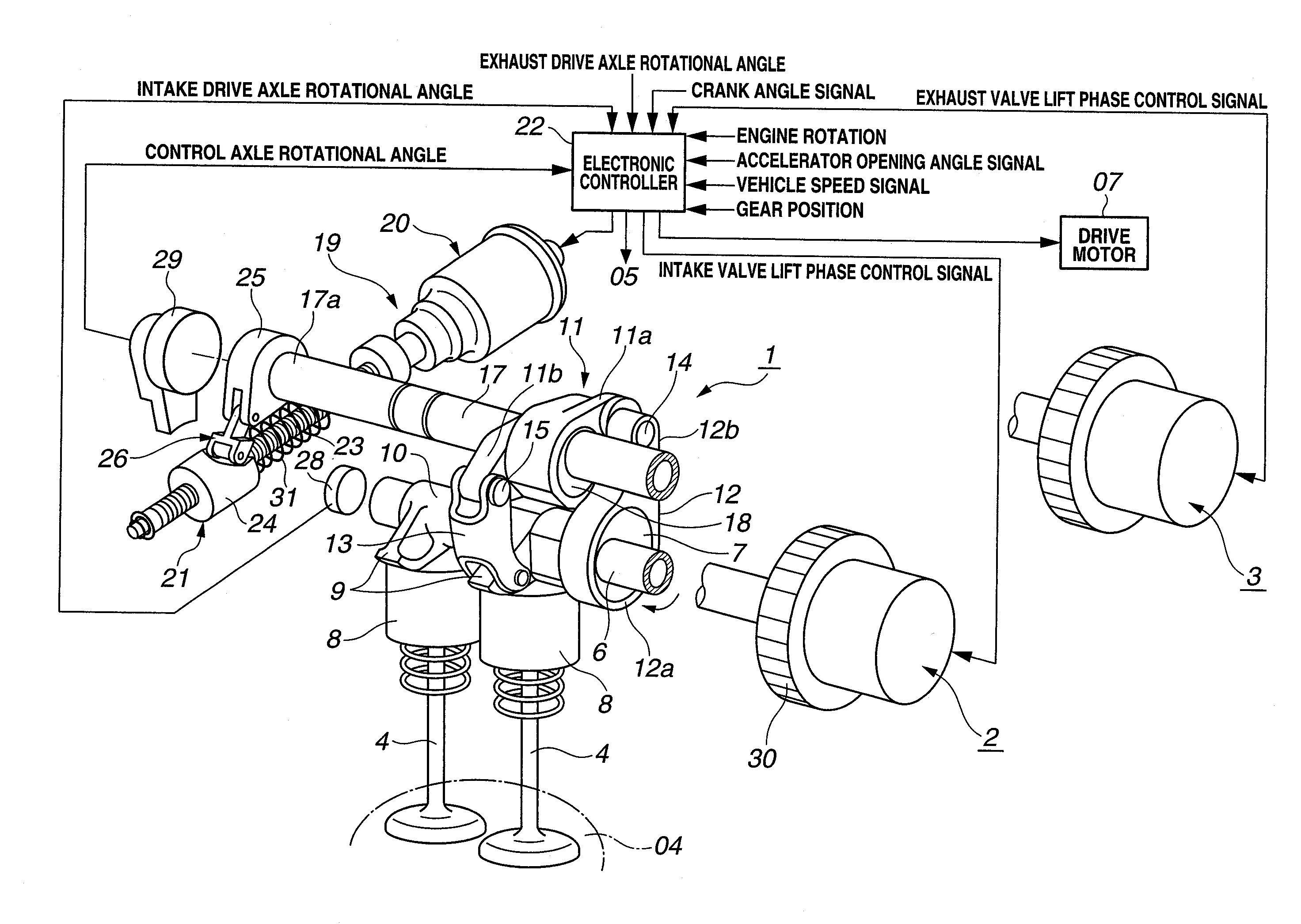
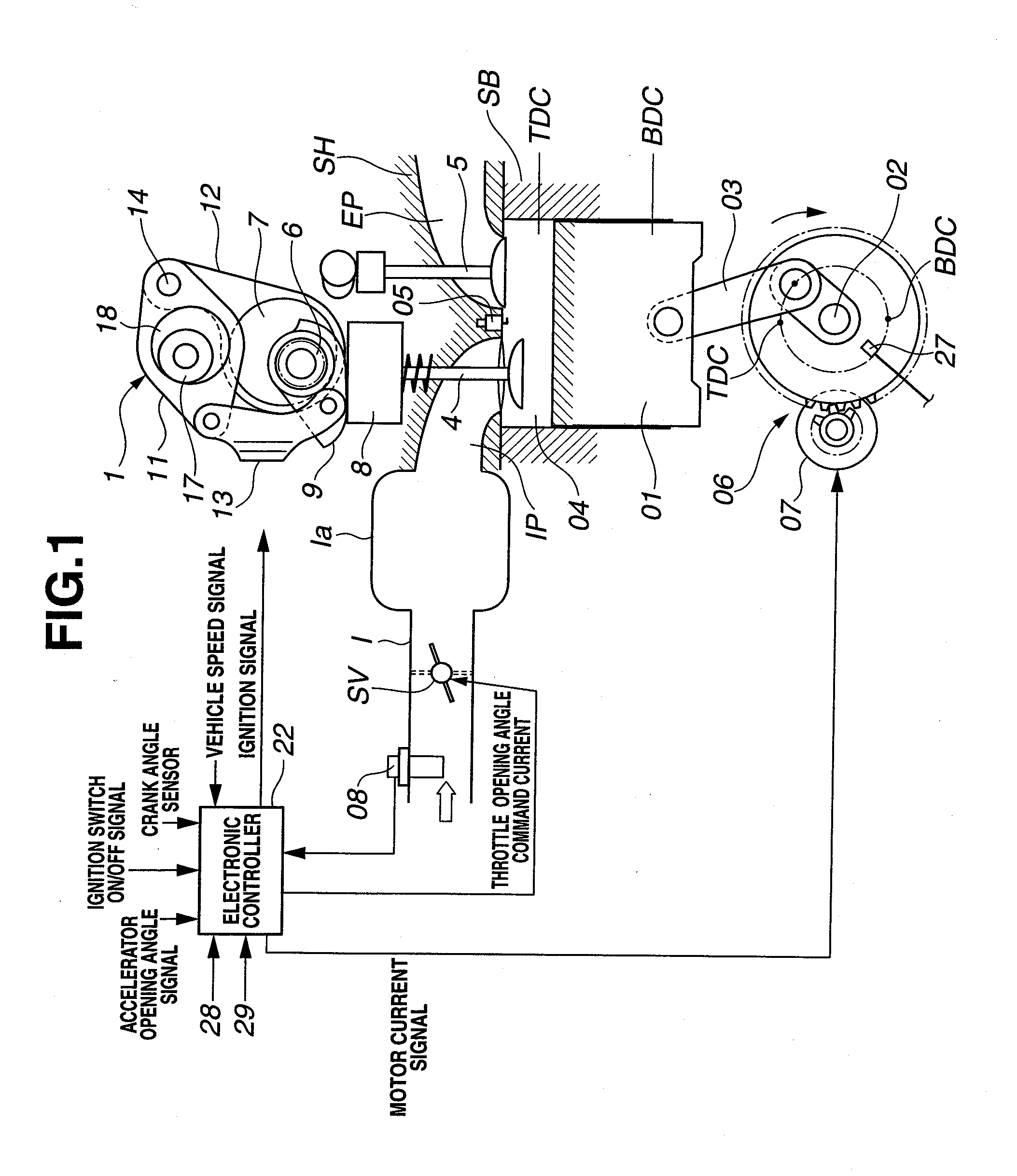
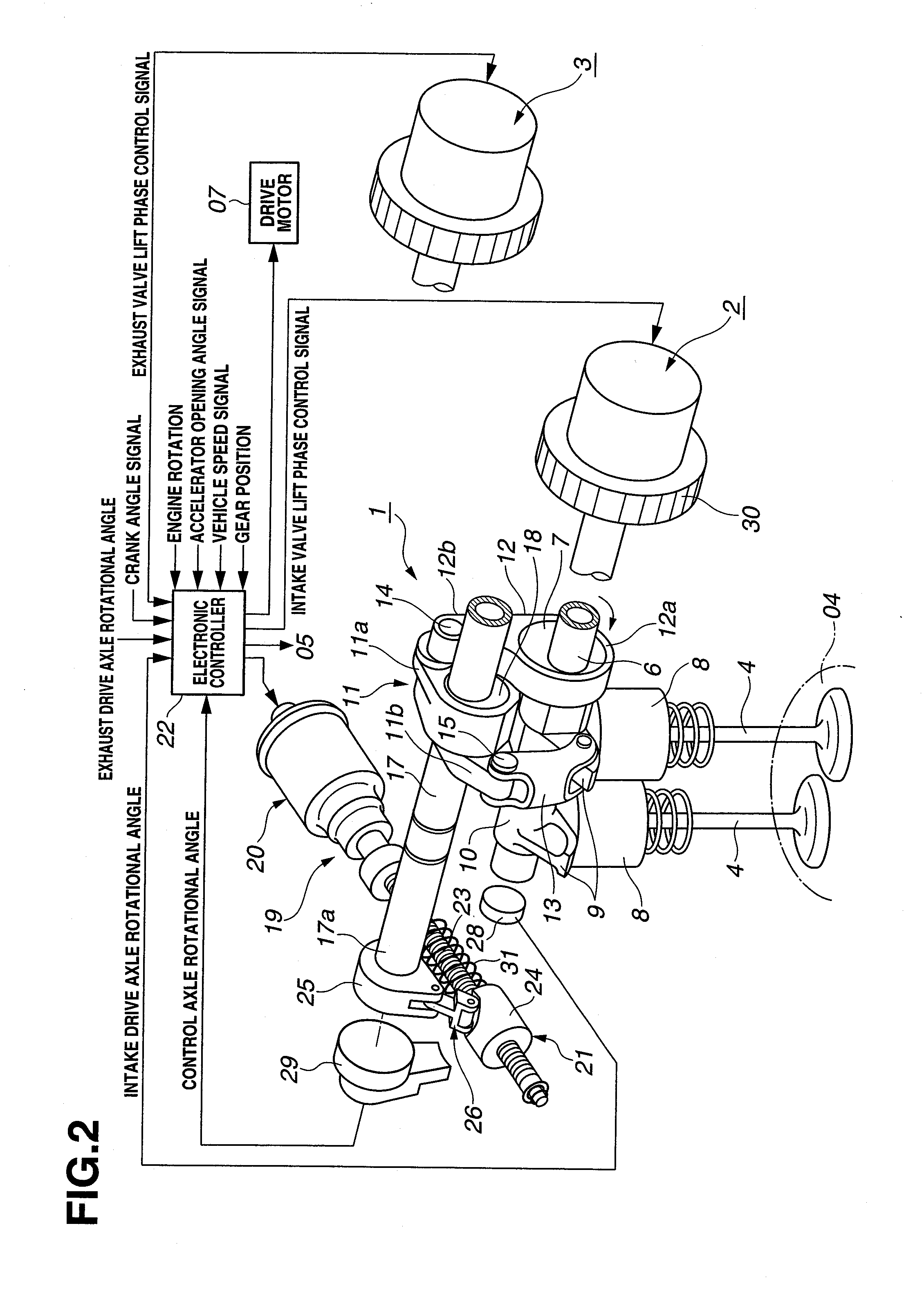
Variably operated valve apparatus for internal combustion engine, start system for internal combustion engine, and start control apparatus for internal combustion engine

a valve apparatus and internal combustion engine technology, applied in the direction of engine starters, machines/engines, output power, etc., can solve the problem of inability to obtain stable engine startability, and achieve the effect of stabilizing the start cranking characteristic and improving engine startability

Inactive Publication Date: 2012-02-16
HITACHI AUTOMOTIVE SYST LTD
View PDF0 Cites 10 Cited by
  • Summary
  • Abstract
  • Description
  • Claims
  • Application Information

AI Technical Summary

Benefits of technology

[0007]The crank position (piston position) at the time of the stop of the engine becomes easy to be dispersed. If the crank position is earlier than the closure timing of the intake valve, the compression is increased along with the thereafter rise in the piston with the closure timing of the intake valve as the atmospheric pressure. If the crank position is later than the closure timing of the intake valve, the compression is increased along with the thereafter rise in the piston with the closure timing of the intake valve as the atmospheric pressure.
[0009]It is, therefore, an object of the present invention to provide a variably operated valve apparatus for an internal combustion engine, a start system therefor, and a start control apparatus therefor which can achieve a stabilization of a top dead center compression by means of a piston, thus the start cranking characteristic being stabilized and an engine startability being improved.

Problems solved by technology

Especially, in the latter case, there is a high possibility that a start cranking characteristic is dispersed due to the dispersion of the crank(shaft) stop position so that a stable engine startability cannot be obtained

Method used


Image

  • Variably operated valve apparatus for internal combustion engine, start system for internal combustion engine, and start control apparatus for internal combustion engine
  • Variably operated valve apparatus for internal combustion engine, start system for internal combustion engine, and start control apparatus for internal combustion engine
  • Variably operated valve apparatus for internal combustion engine, start system for internal combustion engine, and start control apparatus for internal combustion engine

Examples


second embodiment

[0133]FIG. 15 shows a second preferred embodiment according to the present invention. The present invention is applicable to a direct injection type internal combustion engine in which a fuel injection through the fuel injection valve is directly carried out into the corresponding one of cylinders (within combustion chamber 04). Fuel is mainly injected to be ignited and burnt irrespective of the drive by means of drive motor 07 (an unaided or spontaneous combustion) for piston 01 to be pushed down to start the rotation (an unaided or spontaneous start). The other structure is the same as described in the first embodiment.

[0134]The crank position in the first cylinder (#1 cylinder) which is in the compression stroke shown in FIG. 15 is indicated by Z in the same way as shown in FIG. 11 and the closure timing of intake valves 4, 4 is, in the same way as shown in FIG. 11, default IC3.

[0135]It should herein be noted that the cylinder in the expansion stroke is #2 cylinder (second cylind...


PUM


Abstract

A variably operated valve apparatus for use in an internal combustion engine comprises: a variable valve actuator configured to variably adjust at least a closure timing of an intake valve; and a mechanically stabilizing section configured to mechanically stabilize the closure timing of the intake valve at a position more retardation angle side than a most retardation angle position which is a limit of a control range of the stop position of the piston at the time of the stop of the engine. In addition, in start system and start control apparatus for the internal combustion engine, crank position control means controls a stop position of a piston at a position more advance angle side than the closure timing of the intake valve, at a time of stop of the engine.

Description

BACKGROUND OF THE INVENTION[0001](1) Field of the Invention[0002]The present invention relates to a variably operated valve apparatus for an internal combustion engine, a start system therefor, and a start control apparatus therefor which are capable of controlling at least a relationship between a closure timing of an intake valve and a stop position of a piston to enable an improvement in an engine startability.[0003](2) Description of Related Art[0004]A previously proposed variably operated valve apparatus is exemplified by a Japanese Patent Application First Publication No. 2006-125276 published on May 18, 2006 (which corresponds to a Japanese Patent No. 4419800 issued on Dec. 11, 2009).[0005]In the previously proposed variably operated valve apparatus, after an engine start condition is established, a retardation angle control for a closure timing of an intake valve(s) is performed through a valve timing control apparatus in order for a compression in a top dead center of one o...

Claims


Application Information

Patent Timeline
Patent Type & Authority Applications(United States)
IPC IPC(8): F01L1/34
CPCF01L1/053F01L1/3442F01L13/0021F01L13/0026F01L2001/34453F01L2001/34483F02D13/023F02D13/0238F02N99/002F02N2019/008F02P5/1506Y02T10/18Y02T10/12
Inventor NAKAMURA, MAKOTO
Owner HITACHI AUTOMOTIVE SYST LTD
Why Eureka
Try Eureka