Hydrodynamic backup ring

a backup ring and hydrodynamic technology, applied in the direction of engine seals, leakage prevention, machines/engines, etc., can solve the problems of static seals and reciprocating seals that are not suitable for use with rotary seals, and the differential pressure that resilient rotary seals can retain, so as to prevent the collapse of the hydrodynamic recess and the modulus of elasticity

Active Publication Date: 2012-02-16
KALSI ENG
View PDF19 Cites 19 Cited by
  • Summary
  • Abstract
  • Description
  • Claims
  • Application Information

AI Technical Summary

Benefits of technology

[0024]The backup ring can include at least one anti-rotation projection configured to engage a recess of the machine component, in order to prevent rotation of the backup ring with respect to the machine component. The anti-rotation projection can project from an enlarged head that is embedded in the backup ring. The purpose of the enlarged head is to bridge the recess of the machine component, and thereby prevent the backup ring material from entering the recess. The enlarged head preferably has a modulus of elasticity that is greater than the portion of the backup ring that the enlarged head is embedded into.
[0025]The backup ring can include a shoulder positioned adjacent to the hydrodynamic recess, to provide support to the hydrodynamic recess, and help to prevent collapse of the hydrodynamic recess. The shoulder provides an abrupt transition between the hydrodynamic recess and the surrounding dynamic surface of the backup ring. The shoulder can be skewed with respect to the possible directions of relative rotation between the backup ring and the relatively rotatable member, in order to distribute lubricant across the dynamic surface of the backup ring. The backup ring can, if desired, be made in a V-shaped configuration to support a packing ring.

Problems solved by technology

The differential pressure that such resilient rotary seals can retain is limited by the extrusion resistance of the material used in the construction of the seal, and is also limited by the size of the extrusion gap clearance that exists between the seal housing and the mating relatively rotatable surface.
The backup rings that are used with static seals and with reciprocating seals are unsuitable for use with rotary seals that are retaining significant differential pressure due to liabilities such as high friction, high wear, material flow, and damaging frictional heat.

Method used


Image

  • Hydrodynamic backup ring
  • Hydrodynamic backup ring
  • Hydrodynamic backup ring

Examples


Embodiment Construction

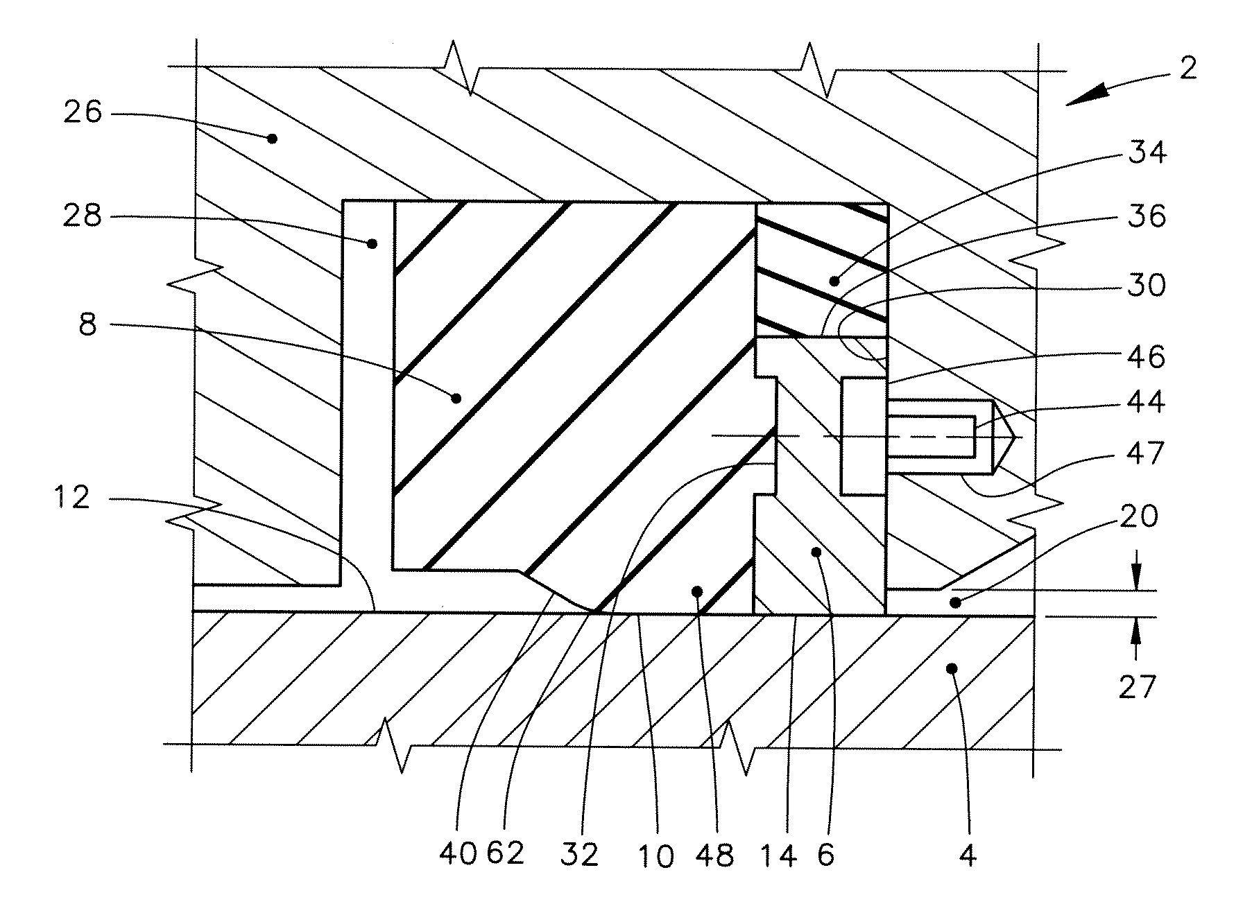
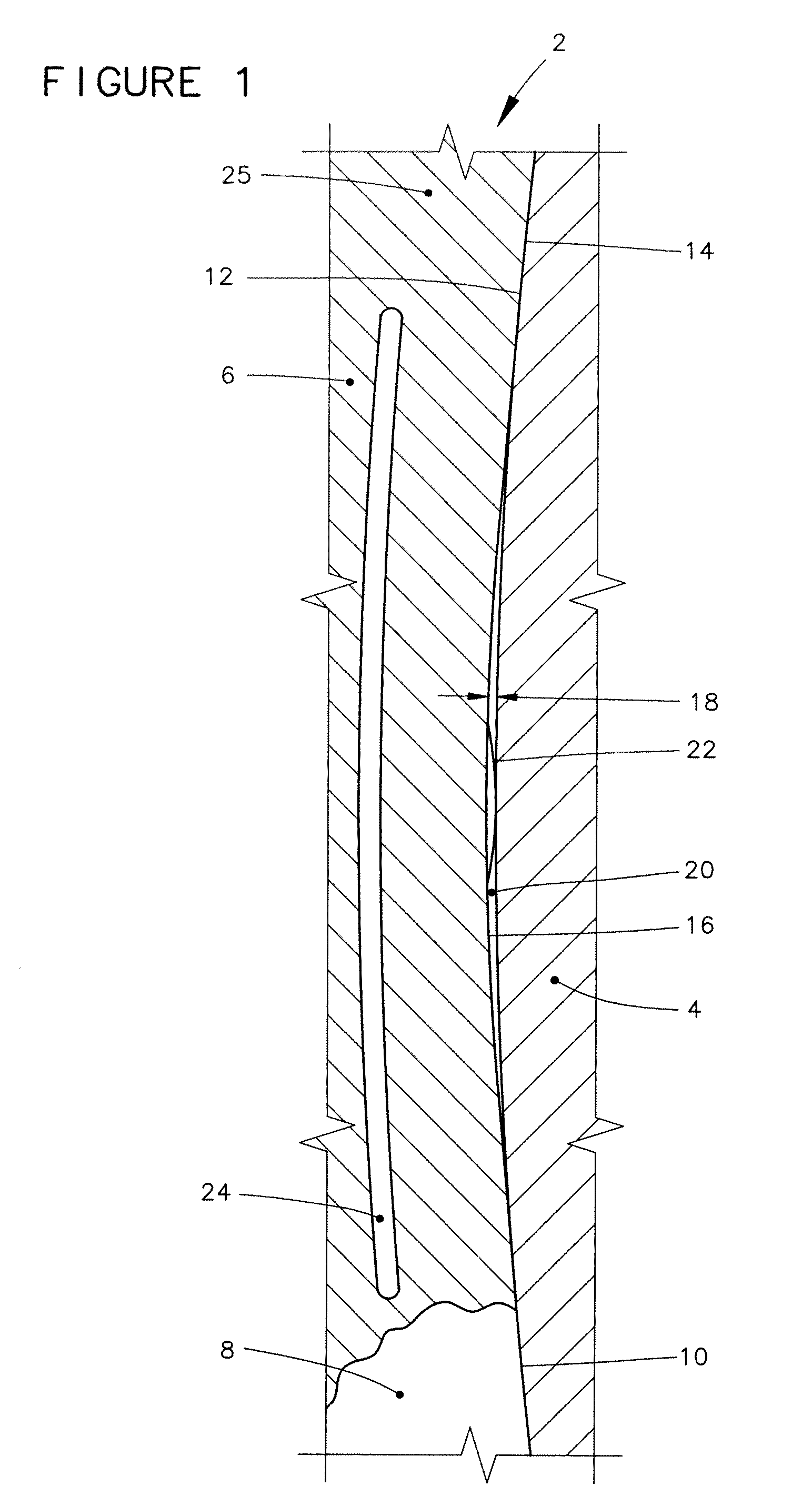
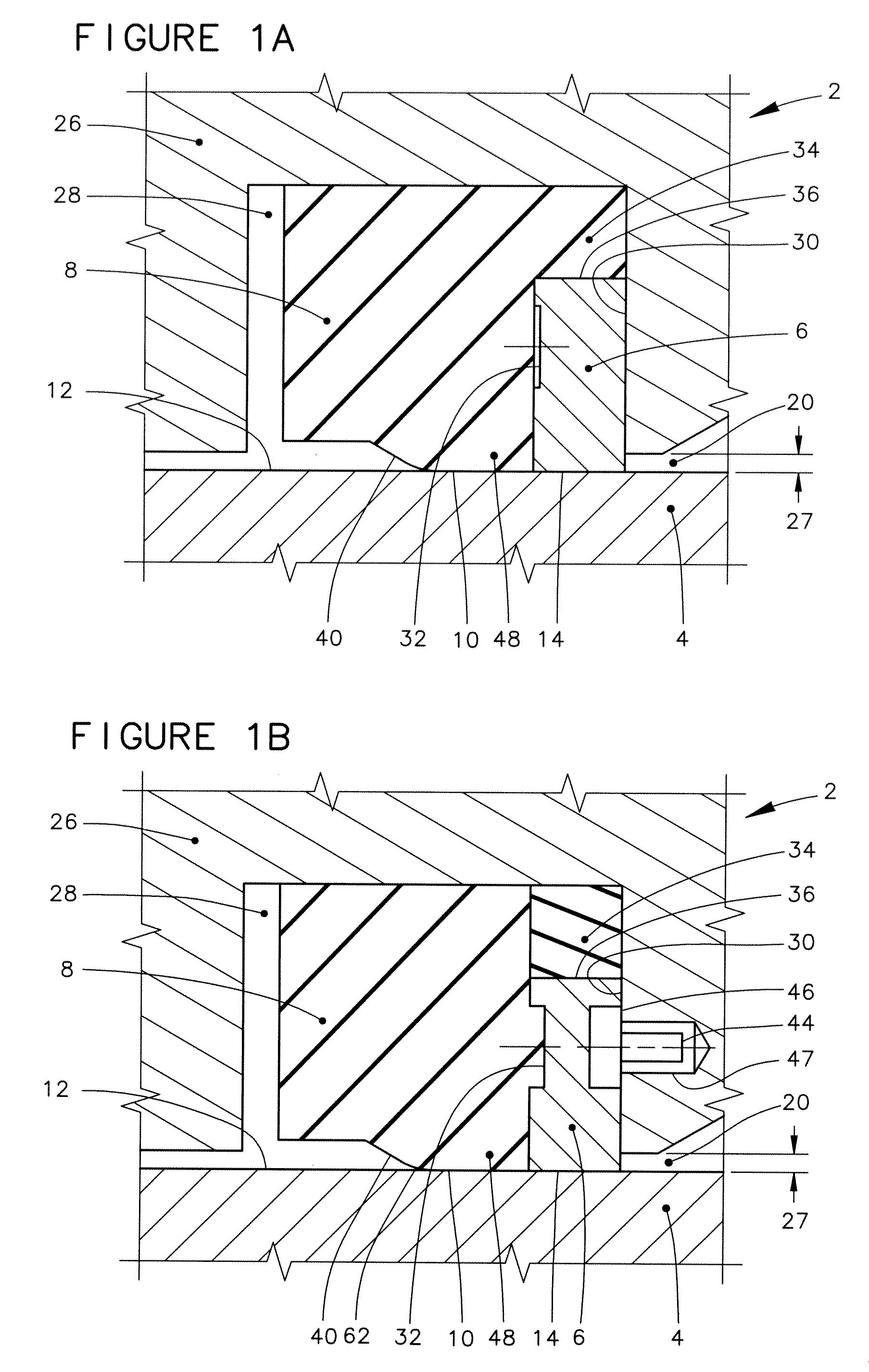
[0061]Features throughout this specification that are represented by like numbers have the same function. Referring now to the drawings and first to FIG. 1, a fragmentary transverse cross-sectional view of a rotary assembly is shown generally at 2 at a greatly enlarged scale.

[0062]The rotary assembly 2 incorporates a relatively rotatable member 4 that is relatively rotatable with respect to a backup ring 6. The backup ring is positioned in supporting engagement with a rotary seal 8. (The cross-sectional illustration of the backup ring 6 is broken away at one location to make a portion of the rotary seal 8 visible.). A dynamic sealing surface 10 of the rotary seal 8 is held in sealing engagement with a relatively rotatable surface 12 of the relatively rotatable member 4.

[0063]By “transverse cross-sectional view,” what is meant throughout this specification is the imaginary cutting plane of the cross-sectional view is oriented at right angles to the theoretical axis of the relatively ...


PUM


Abstract

A seal backup ring is provided with undulating surfaces which create circumferential convergence with a relatively rotatable surface. The backup ring is configured so that differential pressure acting across a rotary seal forces portions of the backup ring against the relatively rotatable surface, closing, or substantially closing, the extrusion gap that the rotary seal is exposed to. In response to relative rotation between the backup ring and the mating relatively rotatable surface, the circumferential convergence promotes hydrodynamic lubrication within the dynamic interface that exists between the backup ring and the relatively rotatable surface. The modulus of elasticity of the backup ring is greater than the modulus of elasticity of the rotary seal.

Description

CROSS-REFERENCE TO RELATED APPLICATIONS[0001]This application claims the benefit of U.S. Provisional Application Ser. No. 61 / 337,667 filed Feb. 11, 2010 and entitled “High Pressure Rotary Seal”.BACKGROUND OF THE INVENTION[0002]1. Field of the Invention[0003]The present invention is related to rotary seals for use with relatively rotatable parts for fluid retention. More particularly, the present invention is related to a backup ring that is configured to increase the ability of a rotary seal to withstand differential pressure.[0004]2. Description of the Related Art[0005]The use of resilient rotary seals for establishing sealing between relatively rotatable machine components for fluid retention is known. The differential pressure that such resilient rotary seals can retain is limited by the extrusion resistance of the material used in the construction of the seal, and is also limited by the size of the extrusion gap clearance that exists between the seal housing and the mating relat...

Claims


Application Information

Patent Timeline
Patent Type & Authority Applications(United States)
IPC IPC(8): F16J15/40F16J15/32F16J15/16
CPCF16J15/166
Inventor DIETLE, LANNIE LAROYRICHIE, AARONGARCIA, JR., VICTORGOBELI, JEFFREY D.SCHROEDER, JOHN ERICK
Owner KALSI ENG
Why Eureka
Try Eureka