
System for write fault protection in a hard disk drive

Inactive Publication Date: 2012-02-16
HITACHI ASIA
View PDF3 Cites 18 Cited by
  • Summary
  • Abstract
  • Description
  • Claims
  • Application Information

AI Technical Summary

Benefits of technology

[0007]The above and other problems are solved and an advance in the art is made by a system for write fault protection in accordance with this invention. A first advantage of a system in accordance with this invention is that write fault detection is improved which, in turn, improves data integrity performance of HDD products. A second advantage is that throughput performance is not significantly affected. A third advantage is that a system in accordance with this invention does not require additional circuitry which reduces the cost. This makes a system in accordance with this invention suitable for incorporation into low end HDD products.
[0009]In accordance with some embodiments, the parameter is the control signal. In accordance with other embodiments, the parameter is the variation of the control signal that may be determined by determining the difference of the current sample of the control signal from a previous sample of the control signal read from memory. The current sample may then be stored as the previous sample of the control signal for use in a subsequent determination of the variation. In accordance with these embodiments, the threshold values should be selected so as to improve write protection performance and not degrade throughput performance.

Problems solved by technology

As the width becomes narrow, the operation of the HDD becomes more susceptible to shock and rotary vibration.
Shocks or outside forces can cause a misalignment of the write head with a track causing data corruption during a write operation commonly referred to as a write fault.
A wrongly positioned head may overwrite data in an adjacent track corrupting the data currently stored in the track and / or the writing the data to an unintended address making the data irretrievable.
However, shock sensors require additional circuitry adding to the cost of the HDD.
This can be problematic especially in lower-end HDDs.
However, it is a problem that as the technology advances, these methods may not detect write fault quickly enough to prevent a write fault.
This problem arises because servo sector numbers may not grow as quickly as TPI increases due to limitation in drive format efficiency and microprocessor bandwidth.

Method used


Image

  • System for write fault protection in a hard disk drive
  • System for write fault protection in a hard disk drive
  • System for write fault protection in a hard disk drive

Examples


Embodiment Construction

[0019]This invention relates to a controller for a hard disk drive. More particularly, this invention relates to a system for write fault protection in a controller of a hard disk drive. Still more particularly, this invention relates to generating write fault signal based upon a comparison of a control signal generated by the controller to a threshold value.

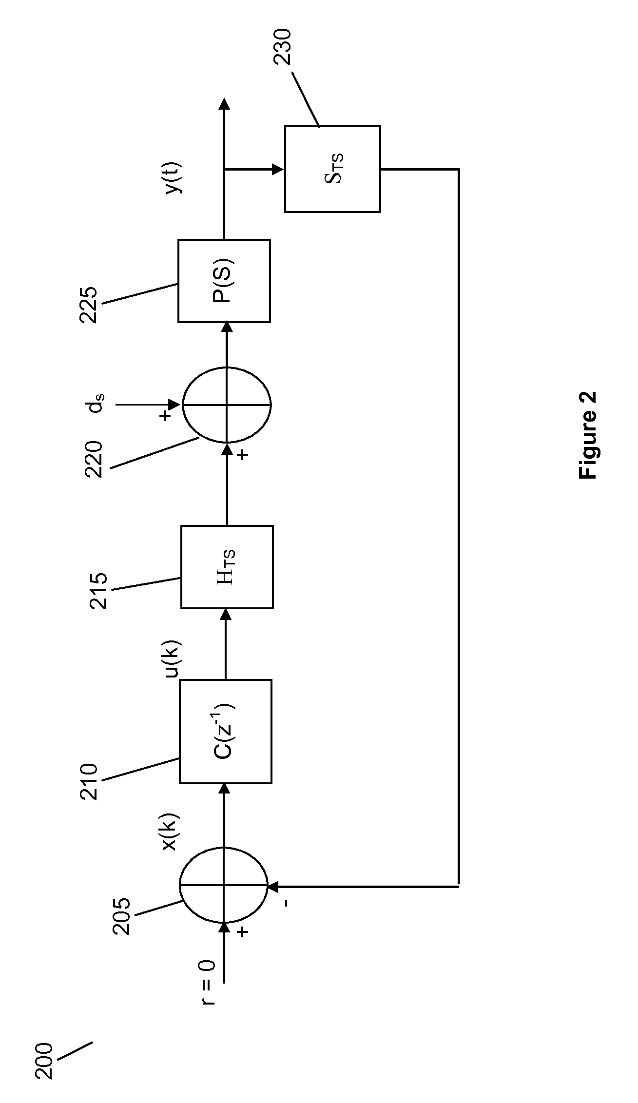
[0020]This invention is a system that performs a process for generating a write fault error signal in response to detection of a write fault. The process may be performed by instructions executed by a processing unit, such a digital signal processor, circuitry or a combination of the two without departing from this invention.

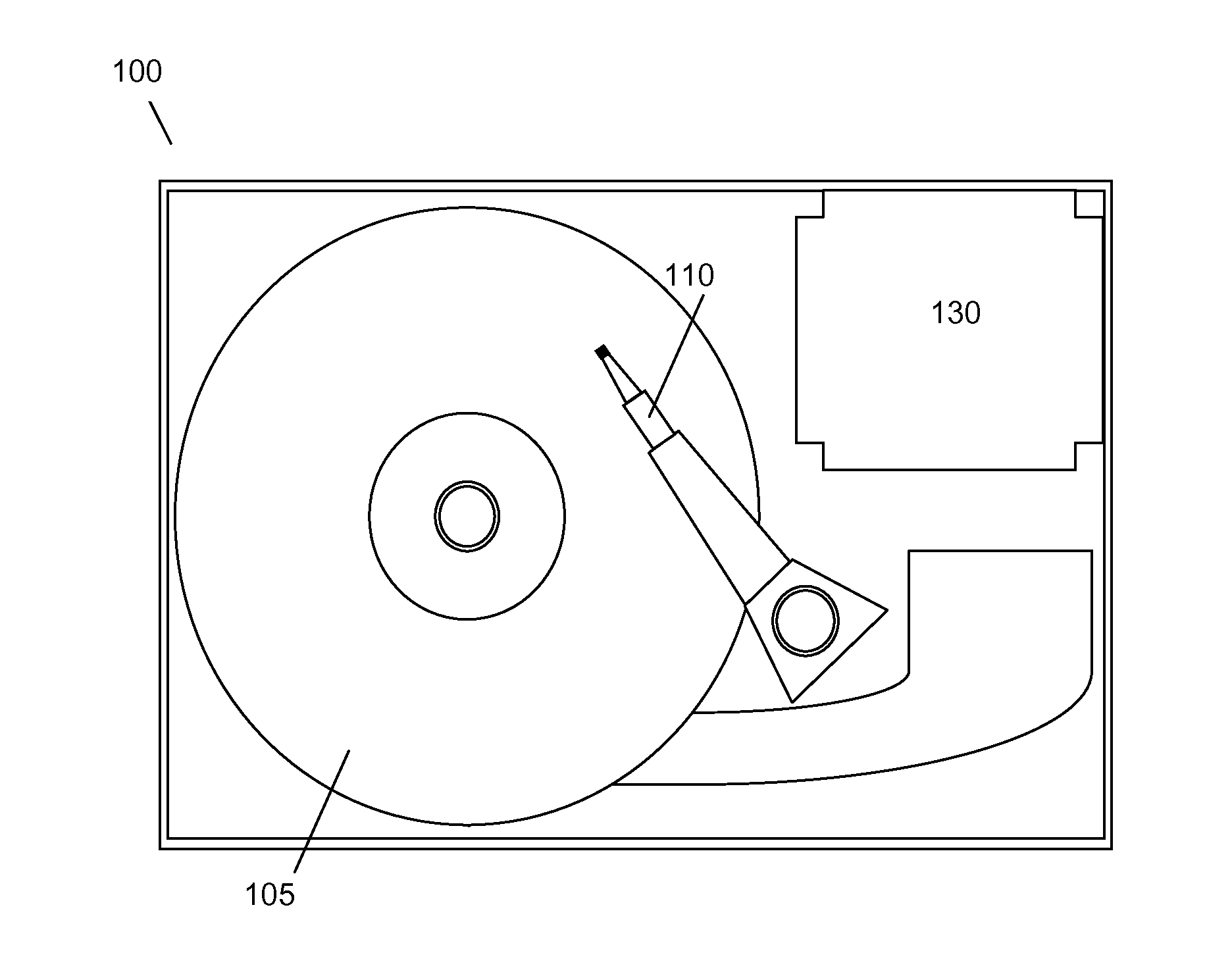
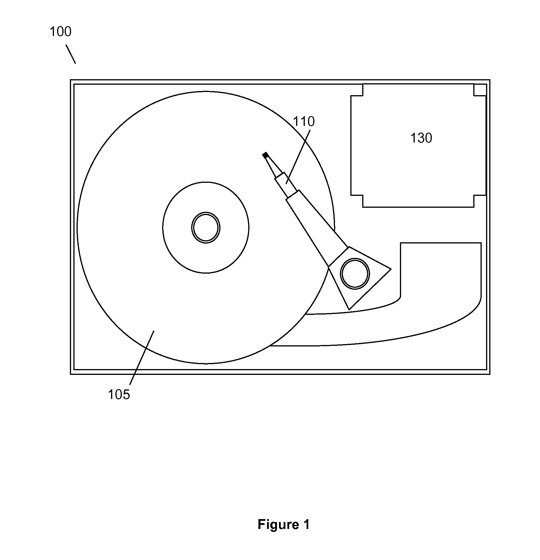
[0021]FIG. 1 illustrates hard disk drive 100 in accordance with this invention. Hard disk drive includes a disk 105 that is rotated by a spinning motor (Not Shown). Read and write heads are connected to a slider at the end of actuator arm 110. Actuator arm 110 moves the slider back and forth over the rotatin...


PUM


Abstract

This invention relates to a system and method performed by a controller in a hard disc drive to generate a write fault signal. The system performs in the following manner. The system begins by receiving a sample of a position error signal. The system then generates a control signal from the position error signal. A sample of the control signal is then captured by the system. The system then determines a parameter to test from the captured sample of the control signal. The absolute value of the parameter is then calculated and compared to a threshold value. The system then generates a write fault error signal in response to a determination that the absolute value of the parameter is greater than or equal to the threshold value.

Description

FIELD OF THE INVENTION[0001]This invention relates to a controller for a hard disk drive. More particularly, this invention relates to a system for write fault protection in a controller of a hard disk drive. Still more particularly, this invention relates to generating write fault signal based upon a comparison of a control signal generated by the controller to a threshold value.SUMMARY OF THE PRIOR ART[0002]Hard Disk Drives (HDD)s are commonly used as a memory device in a wide variety of electronic devices. As the devices become smaller in size, the size of the HDD must also decrease for incorporation into the devices. As the size of HDDs decrease and to increase the amount of memory provided, the data track width and data bit width become narrower to increase the Track Per Inch (TPI) on the disk. As the width becomes narrow, the operation of the HDD becomes more susceptible to shock and rotary vibration.[0003]One particular operation of an HDD that is affected by these outside fo...

Claims


Application Information

Patent Timeline
IPC IPC(8): G11B27/36
CPCG11B20/10009G11B20/10388
Inventor JIA, QING WEI
Owner HITACHI ASIA
Learn More