
Methods and Nodes in a Wireless Communication Network

a wireless communication network and receiver technology, applied in wireless communication, wireless commuication services, baseband system details, etc., can solve the problems of high data rate scenario error floors, very complex jced, and high implementation complexity, so as to improve the performance of wireless communication networks

Inactive Publication Date: 2014-11-27
HUAWEI TECH CO LTD
View PDF3 Cites 24 Cited by
  • Summary
  • Abstract
  • Description
  • Claims
  • Application Information

AI Technical Summary

Benefits of technology

The patent discusses a method for improving wireless communication networks by using adaptive joint iterative channel estimation and decoding. This method takes into account the channel conditions and maximizes throughput by selecting the appropriate soft MIMO detector and controlling the adaptive HARQ buffer controller. The method also utilizes link-quality-metrics, such as a cognitive scheduler and a pre-Turbo decoder, to mitigate errors and improve performance. Additionally, the text mentions the use of the SAGE algorithm, which provides faster convergence compared to other iterative approaches. The overall improvement in signal processing technique facilitates improved performance within the wireless communication network.

Problems solved by technology

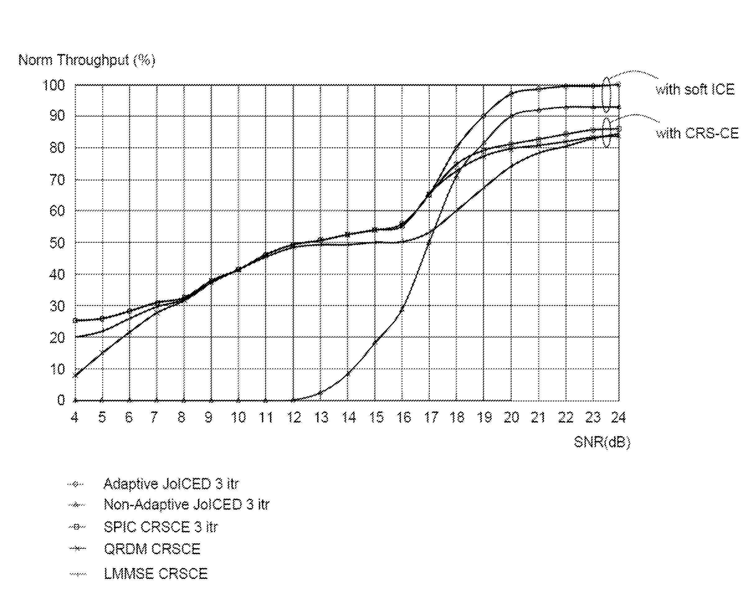
Cell-specific Reference Signals aided Channel Estimation (CRS-CE) unfortunately renders error floors for high data rate scenarios in severe channel conditions, e.g., Extended Typical Urban 300 (ETU300), even though advanced (iterative) MIMO detectors are employed.
Unfortunately, JCED is very complex.
Though JoICED is considered with a tractable complexity, the implementation complexity is evidently very high due to huge matrix inversion online.
Further, non-adaptive JoICED performs very poorly when the soft-data feedback quality is low, such as when the estimated Mutual Information (MI) between the transmitted bits and the soft-data feedback is low.
However, the complexity is formidable and realistically infeasible to implement on the real target for an UE receiver with limited capacity, due to online matrix inversion of considerable size.
However, most of these methods are not really designed for inherent hybrid automatic repeat request (HARQ) based LTE systems.
As mentioned previously, the joint-LMMSE based approach is optimal in the LMMSE sense but infeasible for the UE receiver implementation due to online matrix inversion of significant size, which may involve too capacity-intense calculations for the limited capability of the UE receiver.
Furthermore, the afore-referenced methods render very poor performance when the quality of the feedback soft-data (e.g., in an MI sense which is measured between the transmitted bits and the corresponding soft bits at the receiver side) is very low and thereby have serious detrimental repercussions.
Moreover, the EM / SAGE-MAP framework with low-rank approximation described in the above mentioned prior-art literature is evidently not suitable for higher order modulation when the quality of the feedback soft-data is poor.
Unfortunately, these methods are not that straightforward for LTE, MIMO-OFDM based systems, which inherently have HARQ.
Although this method may be employed in UE receivers, unfortunately, it does not perform very well.
However, EXIT function based activation scheduling has been shown to be inaccurate.
Hence, unfortunately, these known prior-art methods are very cumbersome to employ in a real UE receiver and not straightforward for implementation in a HARQ based system, since scheduling strongly depends on the channel conditions and thus may render poor performance under unfavourable signal propagation conditions.

Method used


Image

  • Methods and Nodes in a Wireless Communication Network
  • Methods and Nodes in a Wireless Communication Network
  • Methods and Nodes in a Wireless Communication Network

Examples


first embodiment

[0067] the time-domain channel coefficients' temporal variations may be approximated via a linear interpolation, or Taylor series, by employing hybrid frequency / time-domain channel estimation. Furthermore, higher order interpolations may also be performed via so-called Polynomial Basis Expansion Method (P-BEM). Linear Interpolation may be viewed as a special case of P-BEM with first order.

second embodiment

[0068]Further, a canonical structure of the so-called full channel frequency response matrix i.e., comprising not only diagonal elements but also the off-diagonal elements within an OFDM symbol, may be used, which is quite elegantly represented in terms of the eigen vectors of the temporal correlation (i.e., intra OFDM symbol correlation).

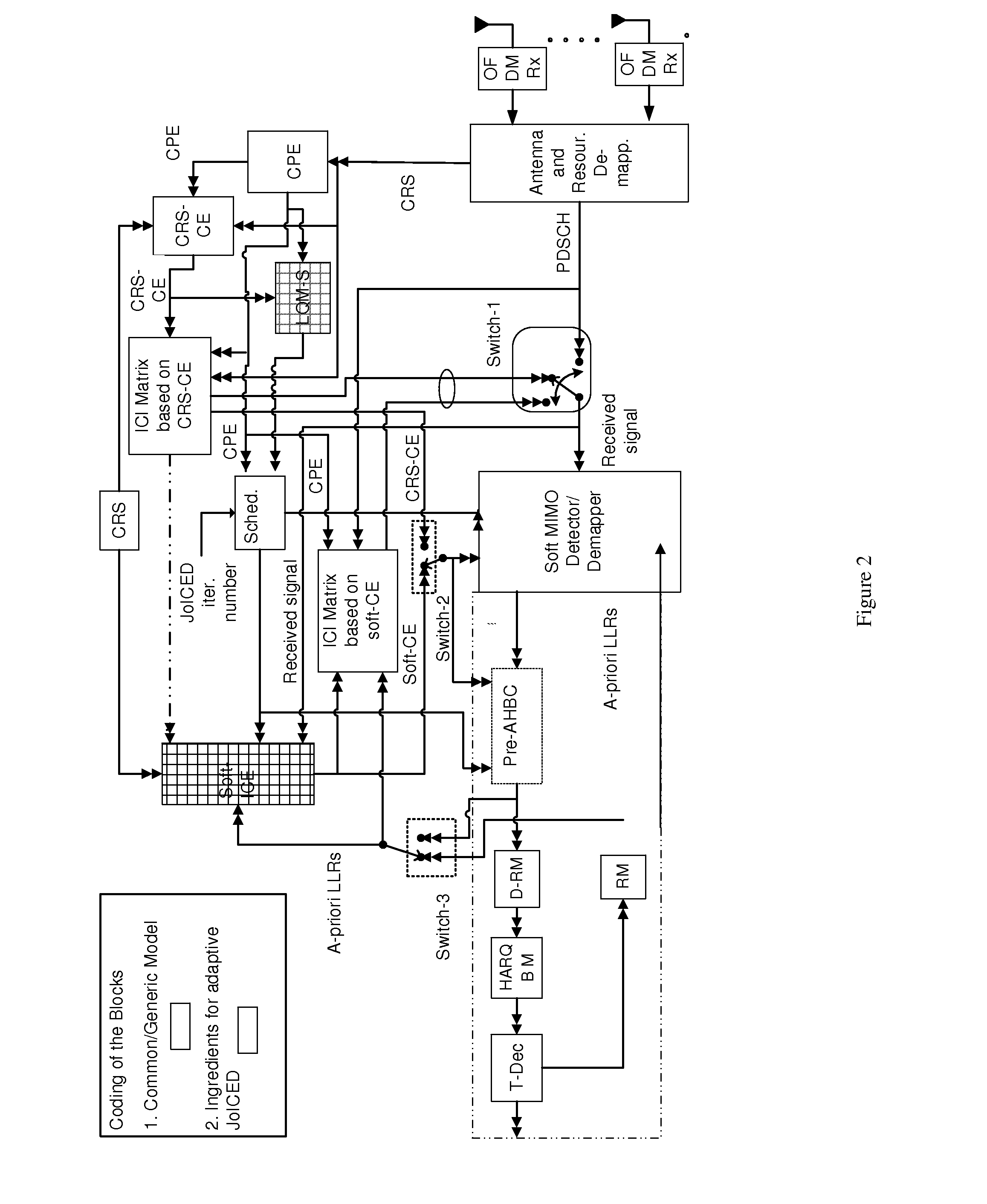
[0069]FIG. 3 depicts a detailed structure of a soft-ICE which utilises a posteriori LLRs output from either TDEC or soft MIMO detector depending on the utilised LQM-H, in particular MI based.

[0070]The basic principle of soft-ICE comprises to re-estimate the channel in case one of the codewords is failing or both codewords are failing. In order to re-estimate the channel, softdata (or partially known data) may be utilised as virtual pilots. Furthermore, as mentioned previously, the quality of soft channel estimates is quite dependent on (or directly proportional to) the quality of the soft-data or a posteriori (APP) LLRs. In other words, when the q...


PUM


Abstract

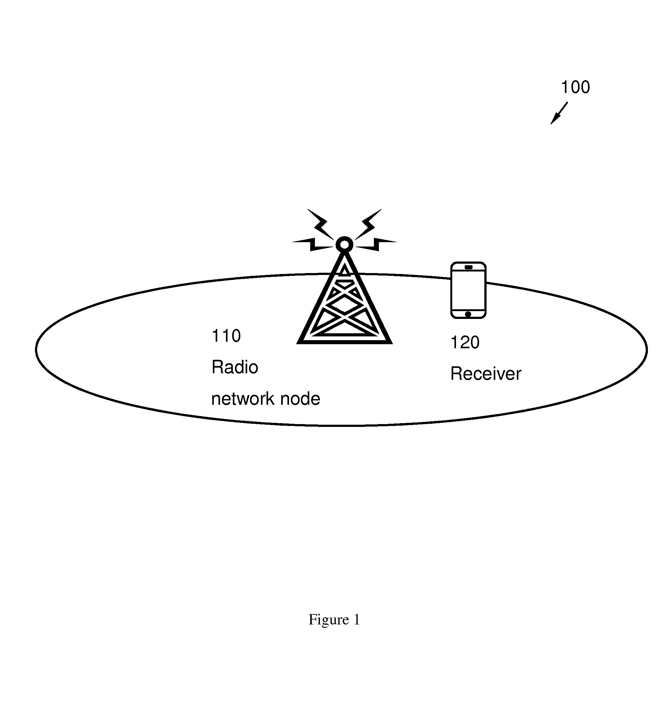
Receiver and method in a receiver, for iterative channel estimation and data decoding of signals received from a radio network node, located in a wireless communication network. The method comprises detecting a signal of the radio network node, performing channel estimation of the detected signal, based on iterative application of a Space Alternating Generalised Expectation and maximisation, SAGE, algorithm, determining a channel / link quality, based on the performed channel estimation and the estimated channel parameters, selecting Multiple-Input and Multiple-Output, MIMO, detector, based on the determined channel quality, determining to enable and / or disable, respectively, soft-Iterative Channel Estimation, soft-ICE, based on the determined channel quality, and iterating the performed channel estimation for a predetermined number of times.

Description

CROSS-REFERENCE TO RELATED APPLICATIONS[0001]This application is a continuation of International Application No. PCT / EP2013 / 057079, filed on Apr. 4, 2013, which is hereby incorporated by reference in its entirety.FIELD OF INVENTION[0002]Implementations described herein relate generally to a receiver and a method in a receiver. In particular is herein described a mechanism for adaptive joint iterative channel estimation and decoding in a wireless communication network.BACKGROUND OF INVENTION[0003]A receiver, also known as User Equipment (UE), mobile station, wireless terminal and / or mobile terminal is enabled to communicate wirelessly in a wireless communication network, sometimes also referred to as a cellular radio system. The communication may be made, e.g., between two receivers, between a receiver and a wire connected telephone and / or between a receiver and a server via a Radio Access Network (RAN) and possibly one or more core networks.[0004]The wireless communication may compr...

Claims


Application Information

Patent Timeline
Patent Type & Authority Applications(United States)
IPC IPC(8): H04L25/02H04W72/08H04L1/00H04B7/04H04W72/54
CPCH04L25/0204H04B7/0413H04L25/0256H04L1/0017H04W72/085H04L1/1835H04L25/025H04L25/03898H04L25/03949H04L25/067H04W72/542
Inventor KANT, SHASHIRUSEK, FREDRIKWU, GENGSHIPRIYANTO, BASUKI ENDAHHU, SHACHEN, JIANJUN
Owner HUAWEI TECH CO LTD
Learn More