
Control device and data storage device

Active Publication Date: 2012-02-16
THE UNIV OF TOKYO
View PDF7 Cites 23 Cited by
  • Summary
  • Abstract
  • Description
  • Claims
  • Application Information

AI Technical Summary

Benefits of technology

[0007]In a control device and a data storage, there would thus be demand for increasing a data write speed.
[0011]In the control device according to this aspect of the invention, the control device has a number of write and erase times counting unit for the second storage configured to count number of write and erase times for the second storage. The number of write and erase times for the second storage is a sum of the number of write times of data in the second storage. The number of erase times of data is stored in the second storage. The control device further has a code length of data setting unit configured to set a data length for execution and a code length for execution to tend to be longer as the number of write and erase times for the second storage increases. The data length for execution is a length of input data from the host device encoded into the error correcting code for the second storage. The code length for execution being a code length of input data from the host device encoded into the error correcting code for the second storage. In the controls device, the memory processing unit for the second storage encodes the input data from the host device into the error correcting code for the second storage having the set data length for execution and the set code length for execution, and the memory processing unit for the first storage performs error correction and decoding on the read data as the error correcting code for the second storage having the set data length for execution and the set code length for execution. The second storage seems to deteriorate with increase of the number of write and erase times for the second storage, and the more error seems to be occurred because it is impossible to write normally in writing data. This is because the second storage is a nonvolatile random access memory. The device sets the data length for execution and the code length for execution to tend to be longer as the number of write and erase times for the second storage increases, encodes the input data from the host device into the error correcting code for the second storage having the set data length for execution and the set code length for execution, and performs error correction and decoding on the read data as the error correcting code for the second storage having the set data length for execution and the set code length for execution. Thus the device is able to collect more errors, and enables the first storage to store more correct data.
[0014]In the control device according to this aspect of the invention, the control devise further has a read processing unit for the first storage configured to control the first storage to read out data stored in the first storage and to output the read data to the host device when a readout request signal requesting to read out data stored in the first storage is input from the host device. The memory processing unit for the first storage encodes the decoded data into an error correcting code for the first storage and controls the first storage to store the encoded data to the first storage. The error correcting code for the first storage correcting more errors than the error correcting code for the first storage corrects. The read processing unit for the first storage performs error correction and decoding on the read data as the error correcting code for the first storage, and outputs the decoded data to the host device. Thus assured error collection and output of more correct data to the host device are accomplished when the error occurs in the data stored in the first storage. Generally, in error correction by an Error Correcting Code, the less number of errors is, the shorter the processing time of error correction is. Also the less number of errors is, the smaller the consumption power for process is. By using error correcting code correcting more errors than the error correcting code for the second storage as the error correcting code for the first storage, i.e., by using error correcting code correcting less errors than the error correcting code for the first storage as the error correcting code for the second storage, compared to using error correcting code same as the error correcting code for the first storage and correcting comparatively more errors as the error correcting code for the second storage, the control device accomplishes the shorter processing time of error correction correcting the read data from the second storage and the smaller consumption power of the error correction.

Problems solved by technology

In this case, a write speed in writing the input data from the PC system to the HDD is limited by a writing speed of the HDD.

Method used


Image

  • Control device and data storage device
  • Control device and data storage device
  • Control device and data storage device

Examples


Embodiment Construction

[0027]One mode of carrying out the invention is described below as a preferred embodiment.

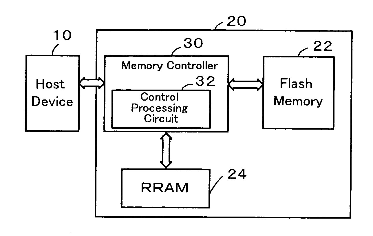
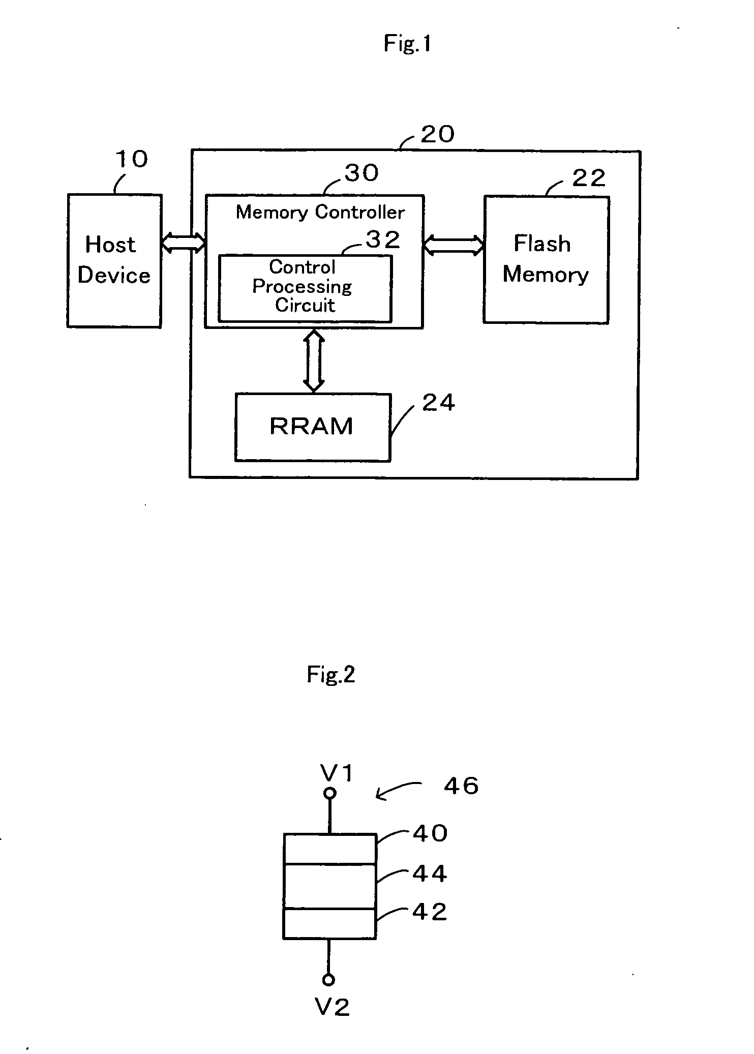
[0028]FIG. 1 schematically illustrates one configuration of a SSD (Solid State Drive) 20 storing data from a host device 10, for example, personal computer. The SSD 20 is configured as a large-capacity data storage storing application programs and data. The SSD 20 has a flash memory 22 configured as a NAND type flash memory, RRAM 24 configure as a resistance random access memory, a memory controller 30 configured as a control device controlling the flash memory 22 and the RRAM 24.

[0029]The flash memory 22 is configured as a NAND type flash memory having a flash memory cell array (not illustrated) that has a plurality of flash memory cells that a threshold voltage varies by electrons injection into a floating gate or by drawing electrons away from the floating gate. In addition to the flash memory cell array, the flash memory 22 has a Law decoder, a column decoder, a sense amplifier and so on (a...


PUM


Abstract

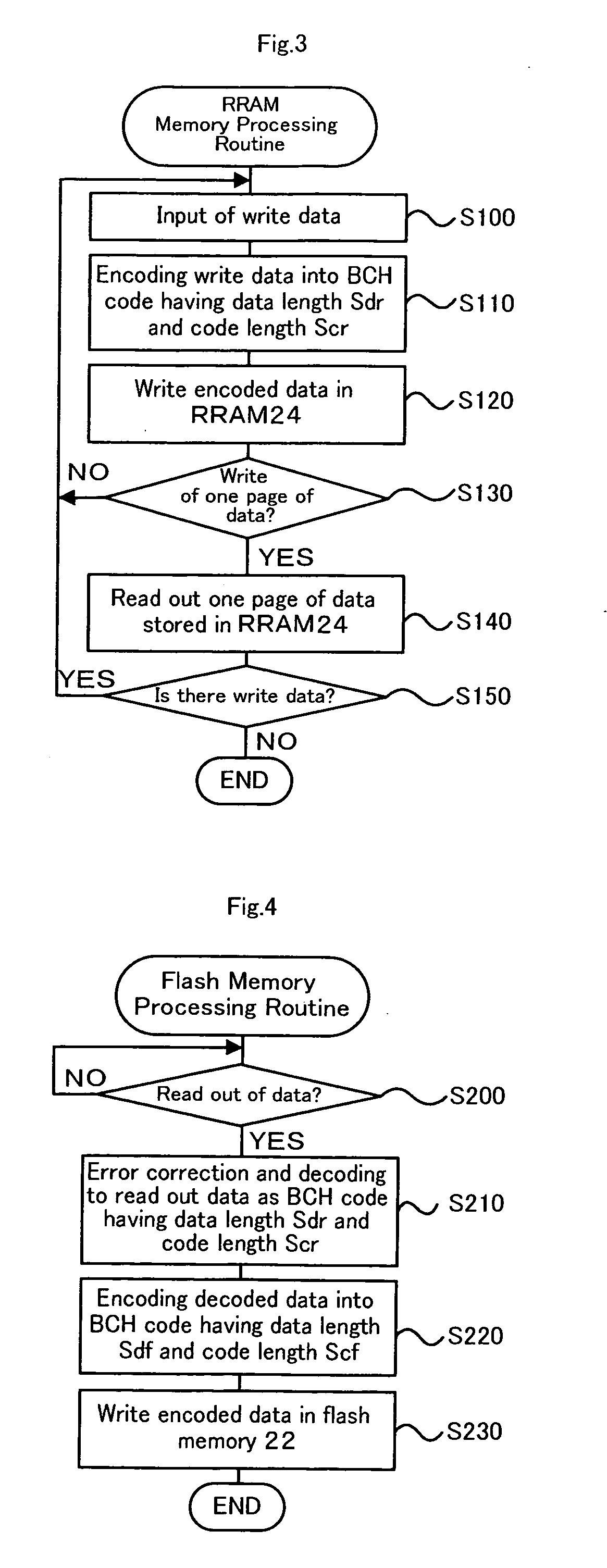
The SSD performs to encode input data from the host device into BCH code having data length Sdr and code length Scr sequentially (step S100 and step S110) and controls RRAM to stores the encoded data (step S120) when the write requesting signal is input from the host device. When the number of BCH code that becomes data of one page of the flash memory after being decoded is stored to RRAM (step S130), the SSD controls RRAM to read out data stored in RRAM (step S140), performs error correction and decoding to the read data as BCH code having the data length Sdr and the code length Scr, and controls the flash memory to store the encoded data.

Description

BACKGROUND OF THE INVENTION[0001]1. Field of the Invention[0002]The present invention relates to a control device and a data storage device, for details, a control device configured to control data transfer between a host device, a first storage configured as a nonvolatile storage for storing data, and a second storage configured as a nonvolatile random access memory having faster write speed than the first storage, and a data storage having such a control device.[0003]2. Description of the Prior Art[0004]One proposed structure of a control device controls a FeRAM (Ferroelectric Random Access Memory) as a cache memory or HDD to store data from a PC system (see, for example, Non-Patent Document 1). In the structure, the FeRAM is configured as a nonvolatile random access memory maintaining data stored therein when a power supply is stopped. In this device, data in the FeRAM is not regularly needed to be evacuated to HDD in preparation to an unexpected stop power supply. This arrangeme...

Claims


Application Information

Patent Timeline
IPC IPC(8): G06F11/16
CPCG06F11/1004
Inventor TAKEUCHI, KENFUKUDA, MAYUMI
Owner THE UNIV OF TOKYO
Learn More