
Control optimization method for helicopters carrying suspended loads

Inactive Publication Date: 2012-02-23
KING FAHD UNIVERSITY OF PETROLEUM AND MINERALS
View PDF5 Cites 23 Cited by
  • Summary
  • Abstract
  • Description
  • Claims
  • Application Information

AI Technical Summary

Benefits of technology

[0013]The control optimization method for helicopters carrying suspended loads during hover flight utilizes a controller based on time-delayed feedback of the load swing angles. The controller outputs include additional displacements that are added to the helicopter trajectory in the longitudinal and lateral directions. This simple implementation requires only a small modification to the software of the helicopter position controller. Moreover, the implementation of this controller does not need rates of the swing angles. The parameters of the controllers are optimized using the method of particle swarms by minimizing an index that is a function of the history of the load swing. Simulation results show the effectiveness of the controller in suppressing the swing of the slung load while stabilizing the helicopter.

Problems solved by technology

Helicopters can be used in carrying heavy loads in civil, military, and rescue operations where the use of ground based equipment would be impractical or impossible.
The global landmine problem is indeed significant, with the United Nations estimating that there are more than 100 million mines in the ground and that 50 people are killed each day by mines worldwide.
If the pendulous motion of the load exceeds certain limits, it may damage the load or threaten the life of the rescued person.
In addition, the aerodynamics of the load may make it unstable in certain flight conditions.
These problems slow or even prevent an accurate pickup or placement of the load.
Moreover, it adds extra effort on the pilot.
The disadvantage was that aerodynamic forces on the cables and the load were neglected, as were the helicopter rotor dynamic modes.
A major disadvantage was that in such a system, a simple linear model representing the yawing and the pendulous oscillations of the slung-load system assumes that the helicopter motion is unaffected by the load.

Method used


Image

  • Control optimization method for helicopters carrying suspended loads
  • Control optimization method for helicopters carrying suspended loads
  • Control optimization method for helicopters carrying suspended loads

Examples


Embodiment Construction

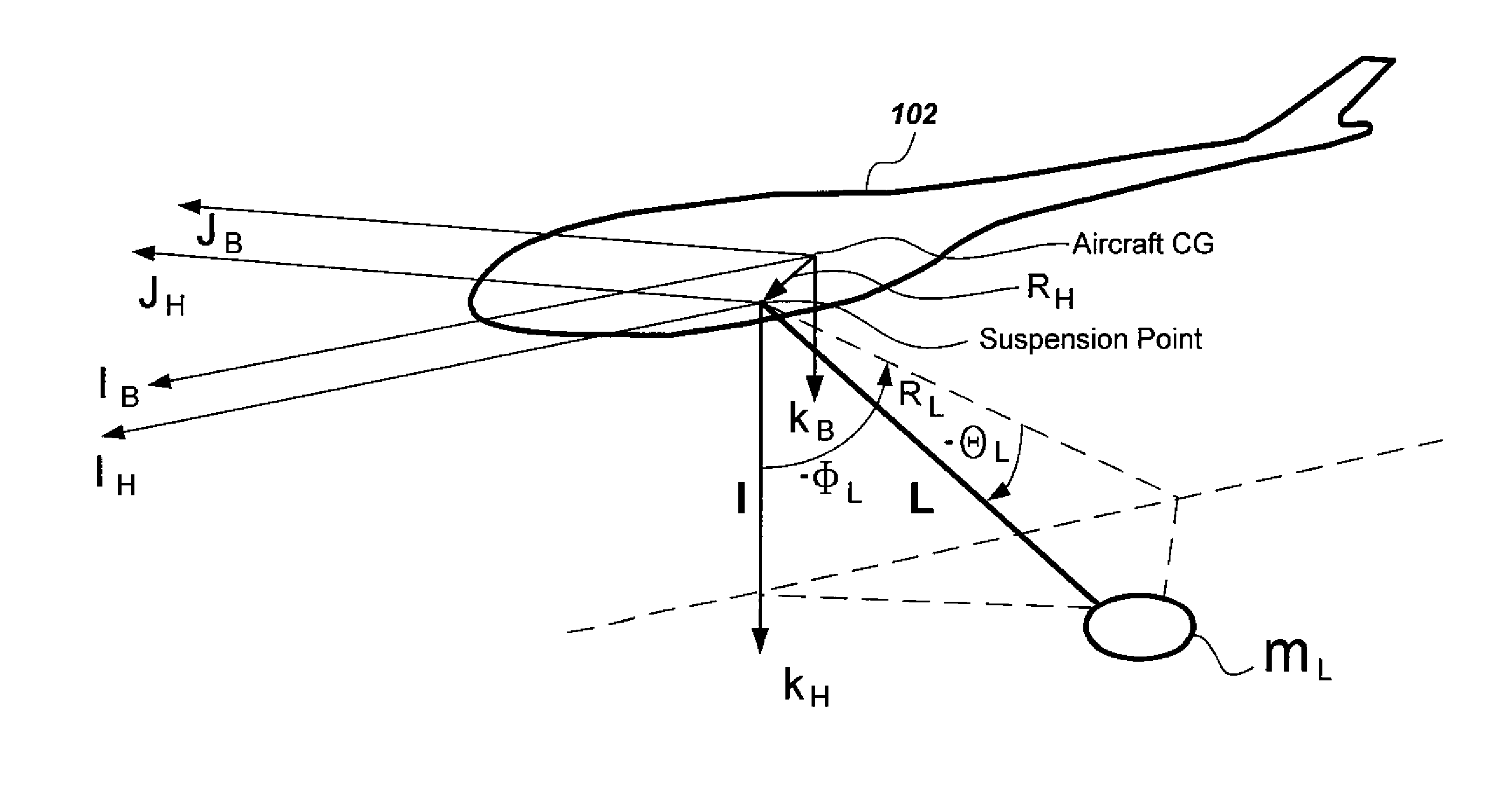
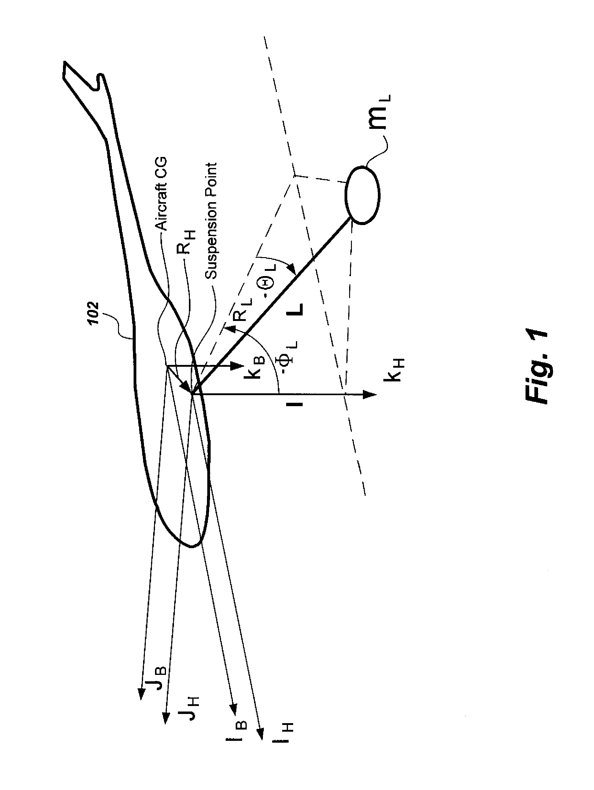
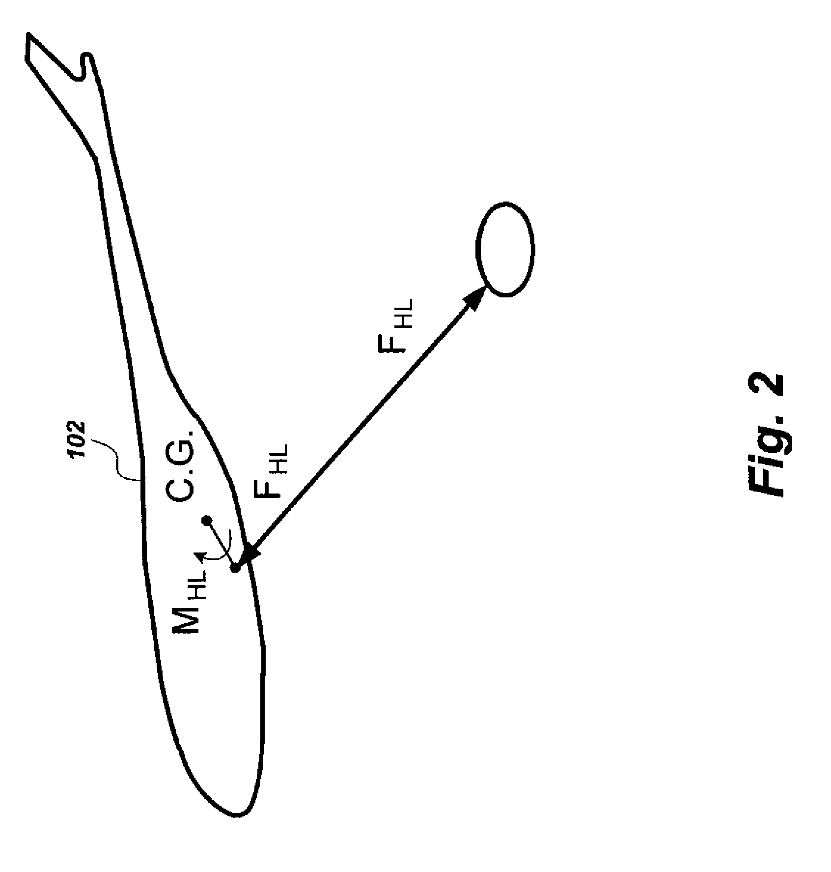
[0025]As shown in FIG. 3, the control optimization method for helicopters carrying a suspended load optimizes a tracking controller 303 and an anti-swing controller 320. As shown in FIGS. 1 and 2, the helicopter with a slung system can be considered as a multi-body dynamical system. The equations of motion of each body can be written alone and then modified by adding the interaction forces between them. At the outset, frequently used equation nomenclature is set forth below, as follows:

[0026]Nomenclature[0027]FHL=Force transferred from the load to the helicopter[0028]kd=gain of the delayed feedback controller[0029]L=load cable length[0030]mL=load mass[0031]MHL=Moment transferred from the load to the helicopter[0032]N=number of particles in PSO[0033]PSO=particle swarm optimization algorithm[0034]RH=hook position vector[0035]RL=load position vector[0036]p,q,r=helicopter angular velocities[0037]Vmax=maximum velocity of PSO particles[0038]u,v,w=helicopter velocities[0039]x,y,z=helicopte...


PUM


Abstract

The control optimization method for helicopters carrying suspended loads during hover flight utilizes a controller based on time-delayed feedback of the load swing angles. The controller outputs include additional displacements, which are added to the helicopter trajectory in the longitudinal and lateral directions. This simple implementation requires only a small modification to the software of the helicopter position controller. Moreover, the implementation of this controller does not need rates of the swing angles. The parameters of the controllers are optimized using the method of particle swarms by minimizing an index that is a function of the history of the load swing. Simulation results show the effectiveness of the controller in suppressing the swing of the slung load while stabilizing the helicopter.

Description

BACKGROUND OF THE INVENTION[0001]1. Field of the Invention[0002]The present invention relates to feedback control system optimization, and more specifically to a control optimization method for helicopters carrying suspended loads that provides an anti-swing feedback control system for the loads carried by the helicopter.[0003]2. Description of the Related Art[0004]Helicopters can be used in carrying heavy loads in civil, military, and rescue operations where the use of ground based equipment would be impractical or impossible. An unmanned small-scale helicopter can be used also in landmine detection application. The global landmine problem is indeed significant, with the United Nations estimating that there are more than 100 million mines in the ground and that 50 people are killed each day by mines worldwide. The idea is to suspend the mine detection equipment as a slung load underneath a low-cost model helicopter, which has the considerable advantage over a ground based vehicle t...

Claims


Application Information

Patent Timeline
IPC IPC(8): G05D1/00
CPCG05D1/102
Inventor OMAR, HANAFY M.
Owner KING FAHD UNIVERSITY OF PETROLEUM AND MINERALS
Learn More