

Antenna unit and electric apparatus including the same
an antenna unit and electric apparatus technology, applied in the direction of resonant antennas, substantially flat resonant elements, radiating element structural forms, etc., can solve the problems of radio wave interference, gain and radiation efficiency of antennas are substantially reduced, and achieve the effect of improving gain and radiation efficiency of antennas
- Summary
- Abstract
- Description
- Claims
- Application Information
AI Technical Summary
Benefits of technology
Problems solved by technology
Method used
Image

Examples
first embodiment
[0044]An antenna unit 100 according to the present invention is now described with reference to FIGS. 1 to 7. In the following description of embodiments, identical or corresponding portions are denoted by the same reference signs, and redundant description is not repeated.
[0045](First Embodiment)
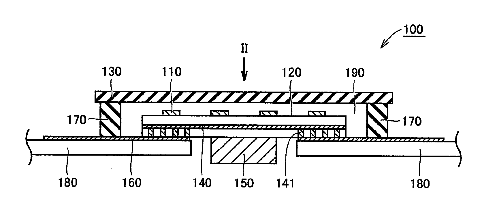
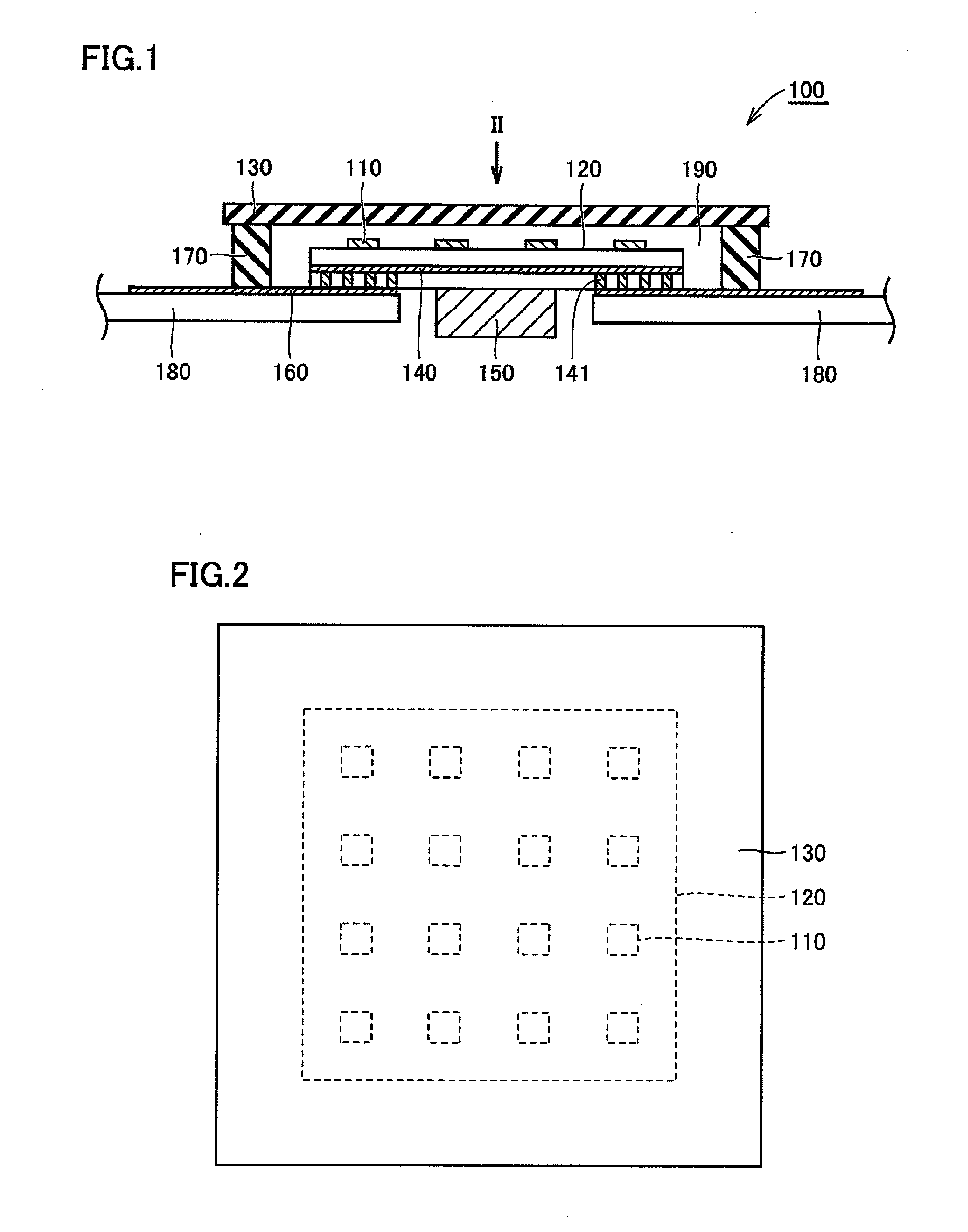
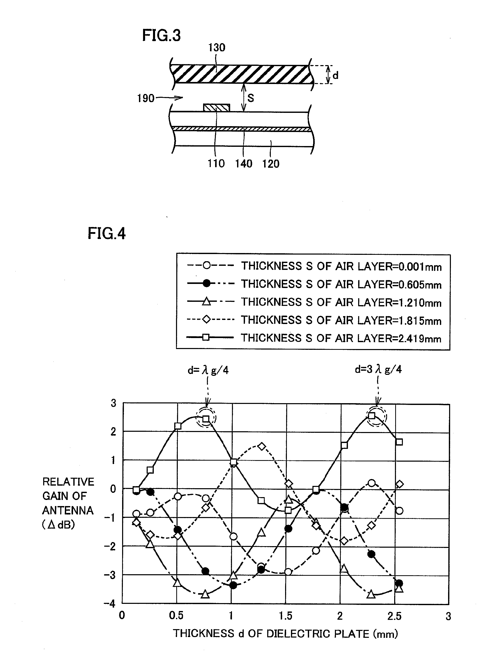
[0046]FIG. 1 is a sectional view showing the structure of antenna unit 100 according to the first embodiment of the present invention. FIG. 2 is a plan view of antenna unit 100 as viewed along arrow II in FIG. 1. FIG. 3 is a sectional view showing antenna unit 100 according to the first embodiment in a partially enlarged manner.
[0047]As shown in FIGS. 1 and 2, a plurality of antennas 110 are formed on the upper major surface of a circuit board 120 in antenna unit 100 according to the first embodiment. According to the first embodiment, circuit board 120 is formed by a ceramic substrate.
[0048]Plurality of antennas 110 are arranged in the form of a lattice at intervals. According to the first...
second embodiment
[0082]An antenna unit according to the present invention is now described.
[0083](Second Embodiment)
[0084]FIG. 8 is a sectional view showing the antenna unit according to the second embodiment of the present invention in a partially enlarged manner. FIG. 9 is a sectional view of the antenna unit taken along the line IX-IX in FIG. 8.
[0085]In the antenna unit according to the second embodiment, a dielectric plate 230 is constituted of a flat plate portion 231 and a protrusion 232, as shown in FIGS. 8 and 9. The remaining structure of the antenna unit according to the second embodiment is similar to that of antenna unit 100 according to the first embodiment, and hence redundant description is not repeated.
[0086]As shown in FIG. 8, protrusion 232 protrudes to approach an antenna 110 in a portion of flat plate portion 231 opposed to antenna 110. According to the second embodiment, flat plate portion 231 and protrusion 232 are integrally made of polypropylene. However, flat plate portion 2...
third embodiment
[0111](Third Embodiment)
[0112]FIG. 21 is a schematic diagram showing a used mode of an electric apparatus according to a third embodiment of the present invention. FIG. 22 is a sectional view showing the structure of the electric apparatus according to the third embodiment.
[0113]As shown in FIG. 21, the electric apparatus according to the third embodiment is constituted of a transmitter 410 and a receiver 510 performing radio transmission between a Blu-ray and HDD (hard disk drive) recorder 400 and a television 500 used indoors.
[0114]Transmitter 410 is connected with Blu-ray and HDD recorder 400, which transmits a signal to transmitter 410. Receiver 510 is connected with television 500, and transmits a signal received therein to television 500.
[0115]In the electric apparatus according to the third embodiment, transmitter 410 transmits a high-frequency signal 430 to receiver 510 through an indoor wall. In general, television 500 is arranged along the wall, and Blu-ray and HDD recorde...
PUM
 Abstract
Description
Claims
Application Information