

Optical imaging apparatus and method for imaging an optical image
- Summary
- Abstract
- Description
- Claims
- Application Information
AI Technical Summary
Benefits of technology
Problems solved by technology
Method used
Image

Examples
embodiments
Exemplary Embodiment 1
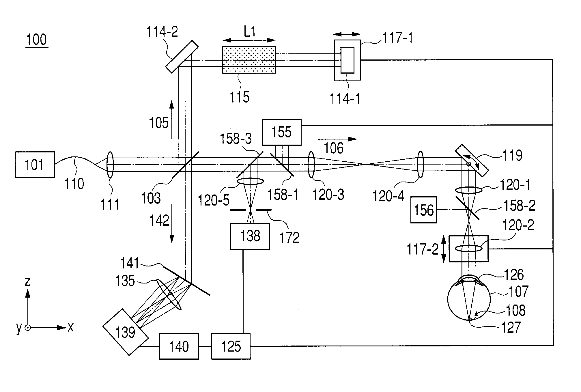
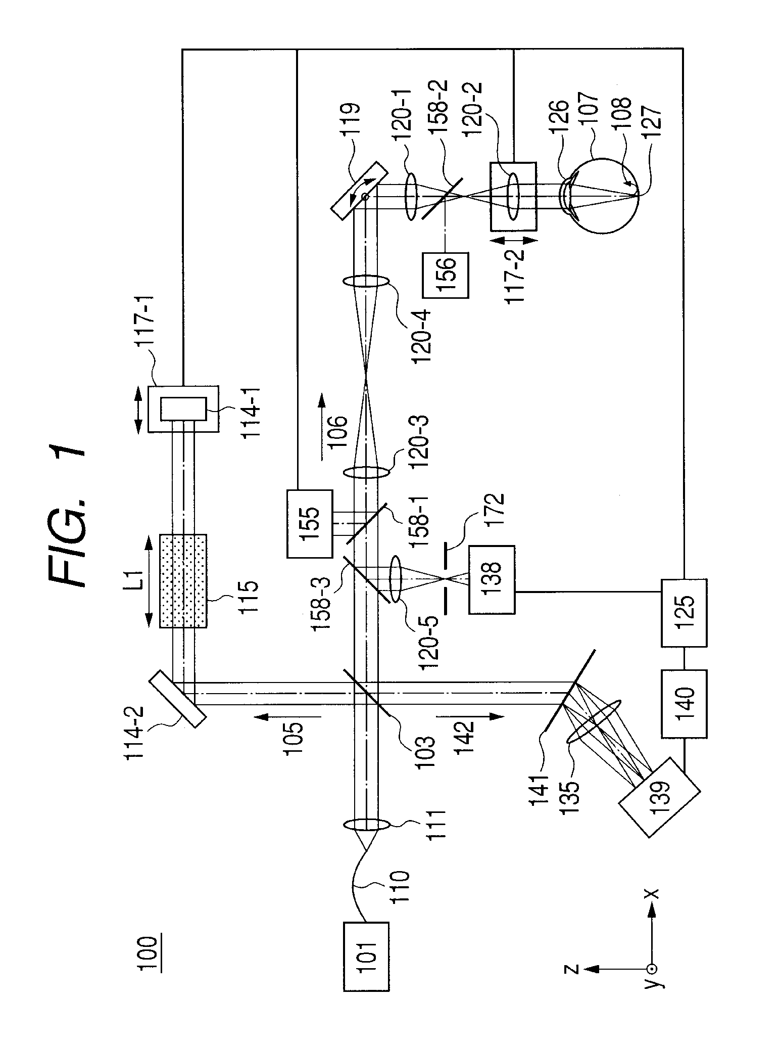
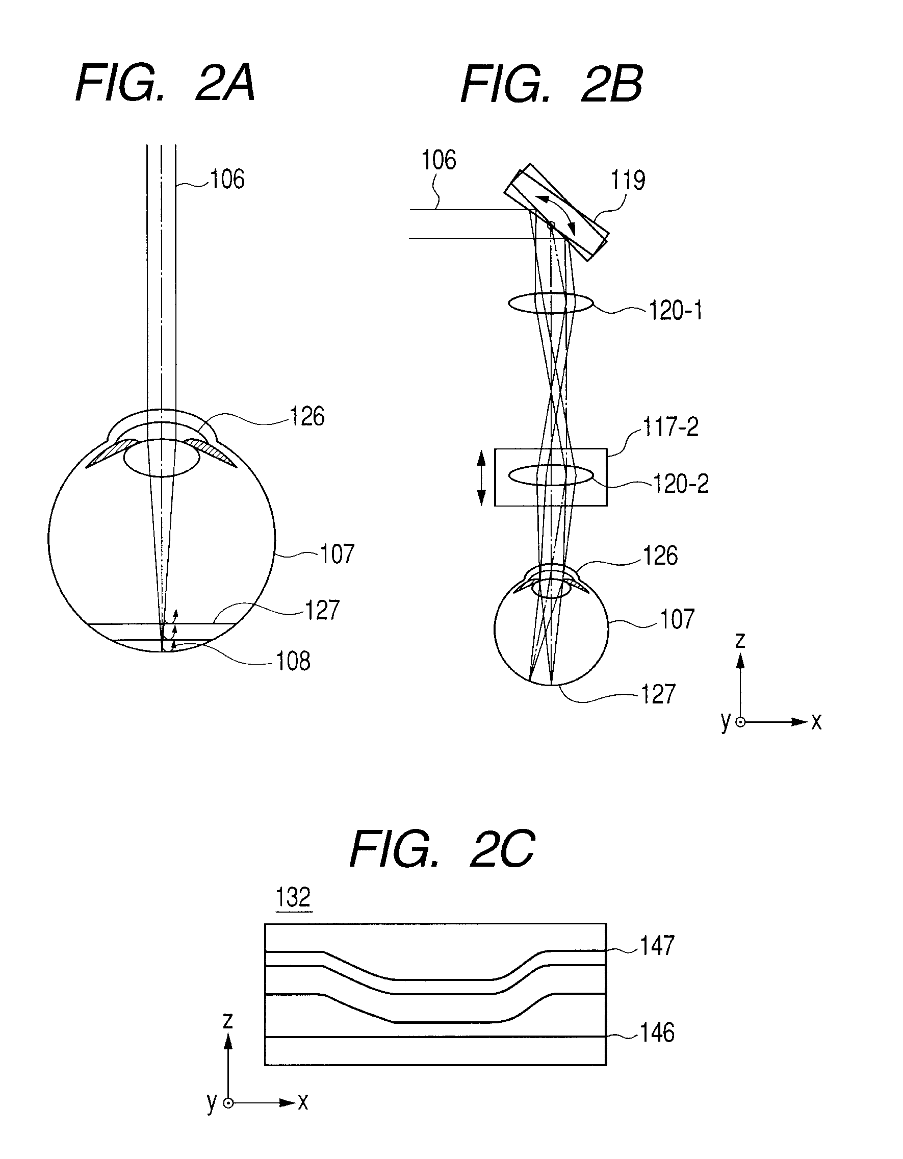
[0016]A first exemplary embodiment describes an OCT apparatus to which the present invention is applied. Particularly, here, there is given a description of an OCT apparatus with a high lateral resolution and capable of imaging both of a planar image (SLO image) and a tomographic image (OCT image) of an eye to be inspected. In this exemplary embodiment, an optical imaging apparatus is adapted so that a measuring beam from a light source is irradiated to an object, and a planar image and a tomographic image of the object are imaged based on light intensity of a return beam formed of the measuring beam irradiated to the object. Particularly, the beam from the light source is split into a measuring beam and a reference beam, and a return beam formed of the measuring beam irradiated to the object and the reference beam traveling through a reference light path are combined to interfere with each other, and then a tomographic image of the object is provided based on ...
exemplary embodiment 2
[0035]A second exemplary embodiment describes an OCT apparatus to which the present invention is applied. Here, particularly, there is given a description of an OCT apparatus with a high lateral resolution for imaging a tomographic image (OCT image) of an eye to be inspected. The present exemplary embodiment provides an OCT apparatus of the Fourier Domain system for acquiring a tomographic image by correcting an aberration, generated in the eye to be inspected, of a measuring beam or a return beam are inspected using a deformable mirror (as an aberration correcting device of the present embodiment), and the OCT apparatus is adapted so that a good tomographic image can be provided regardless of a diopter scale and / or an aberration of the eye to be inspected. Referring to FIG. 5, first, there is given a description of a whole, schematic configuration of an optical system of an OCT apparatus in the exemplary embodiment. In FIG. 5, a similar component to that of the first exemplary embo...
exemplary embodiment 3
[0052]A third exemplary embodiment describes an OCT apparatus to which the present invention is applied. In this embodiment, particularly, there is given a description of an OCT apparatus with a high lateral resolution for imaging a tomographic image (OCT image) of an eye to be inspected. The present exemplary embodiment provides an OCT apparatus of the Fourier Domain system for acquiring a tomographic image by correcting an aberration in an eye to be inspected using a deformable mirror (as an aberration correcting device of the present embodiment), and the OCT apparatus is adapted so that a good tomographic image can be provided regardless of a diopter scale and / or an aberration in the eye to be inspected. In the exemplary embodiment, a whole optical system includes a reflective optical system mainly using spherical mirrors. Referring to FIG. 8, first, there is given a description of a whole, schematic configuration of an optical system of an OCT apparatus in the exemplary embodime...
PUM
 Abstract
Description
Claims
Application Information