
Flexographic printing members

a technology of printing members and printing plates, applied in the field of flexographic printing, can solve the problems of high impression pressure, limited efficiency of flexographic printing plates, and physical limitations of relief image creation process in printing members, so as to improve highlights, improve the effect of flexographic printing, and minimal loss of resolution or edge definition

Inactive Publication Date: 2012-03-01
EASTMAN KODAK CO
View PDF8 Cites 17 Cited by
  • Summary
  • Abstract
  • Description
  • Claims
  • Application Information

AI Technical Summary

Benefits of technology

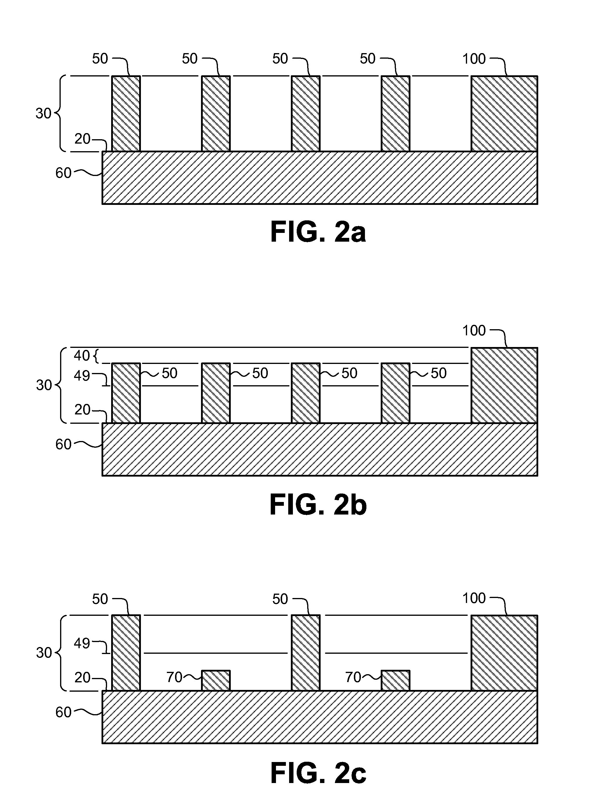
[0027]The present invention provides improved flexographic printing members using a flexographic screening method that combines AM and FM screening with engagement modulation (EM) through control of undercutting of predetermined halftone dots in an image area of a relief image, to improve highlights with minimal loss of resolution or edge definition. On press, the gap between the elastomeric topmost surface of the flexographic printing member and a receiver element is adjusted to optimize print density. This gap is referred to as the engagement and creates the inking pressure (also known as “impression pressure”) between the flexographic printing member and the receiver element to be printed. There is another gap controlled separately on press between the surface of the topmost surface of the flexographic printing member and the Anilox roller used to ink the plate, also referred to as engagement. To extend the tonal range, a plurality of flexographic printing member dots [(b) dots] representing a highlight are undercut to different depths below the elastomeric topmost surface with either a random, pseudorandom, or a predetermined pattern. For example, two or more different depths of undercutting can be selected from a range of depths greater than zero (no undercutting) to a maximum undercutting depth (Umax) to reproduce a given highlight level on the printed receiver sheet. In any given sub-area of the printing plate representing a highlight, at least a small fraction of the dots [(a) dots] in the sub-area are not purposely undercut in order to provide a local topmost surface that is essentially coincident with the topmost surface of the printing plate to control the local pressure with a given engagement, thus relieving pressure on the local undercut dots and facilitating local engagement modulation.
[0028]In some embodiments, many different depths of undercutting are used in a plurality of halftone dots in a sub-area of the elastomeric topmost surface, representing a highlight. Umax is determined by the maximum undercut depth that leaves the halftone dot with a non-zero probability to transfer ink to a receiver element on press with a given set of inking and press conditions. Umax depends upon many factors including the engagement setting of the printing plate and the Anilox cylinders on the printing press. By modulating the depth of the undercutting in a selected plurality of dots, the engagement and therefore the inking pressure and printing pressure are modulated dot to dot. A minimum dot size, Smin, (defined below) is selected in order to prevent the formation of halftone dots that are too small to achieve the purpose of this invention.

Problems solved by technology

Both these methods involve a developing treatment that requires the use of large quantities of liquids and solvents that subsequently need to be disposed of In addition, the efficiency in producing flexographic printing plates is limited by the additional drying time of the developed plates that is required to remove the developing liquid and dry the plate.
While the quality of articles printed using flexographic printing plates has improved significantly as the technology has matured, physical limitations related to the process of creating a relief image in a printing member still remain.
Therefore, the flexographic printing process is highly sensitive to the impression pressure that may affect the resulting image.
If the impression pressure is too high, some image areas can be squeezed, and if it is too low, ink transfer is insufficient.
In particular, it is very difficult to print graphic images with fine dots, lines, and even text using flexographic printing members.
Maintaining small halftone dots on a flexographic printing member is very difficult due to the nature of the plate making process and the small size and lack of stability in the halftone dots.
The smallest of these halftone dots are prone to being removed during processing, which means no ink is transferred to these areas during printing (the halftone dot is not “held” or formed on the printing plate or on the printing press).
Alternatively, if the small halftone dots survive processing, they are susceptible to damage on press.
For example, small halftone dots often fold over or partially break off during printing, causing either excess ink or no ink to be transferred.
However, this results in a loss of the dynamic range and detail in the highlight and shadow areas.
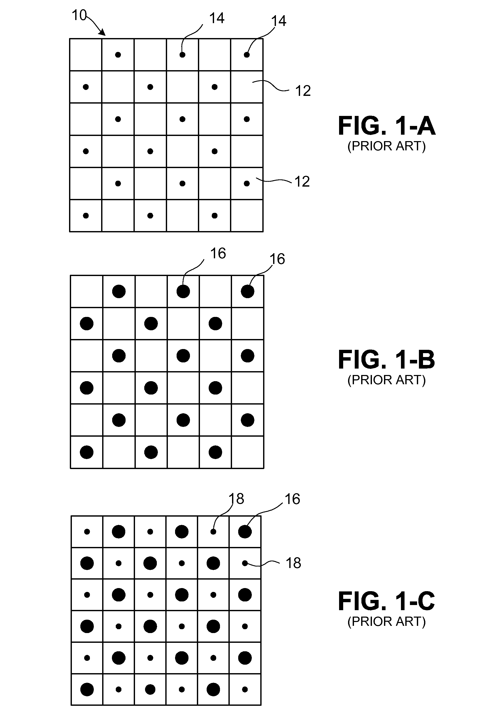
This creates a problem in the highlight areas when using conventional AM screening since once the minimum halftone dot size is reached, further size reductions will generally have unpredictable results.
If, for example, the minimum size halftone dot that can be printed is a 50×50 μm square dot, corresponding to a 5% tone at 114 lines per inch screen frequency, then it becomes very difficult to faithfully reproduce tones between 0% and 5%.
However, a disadvantage of this practice is the resulting additional dot gain in the highlights that causes a noticeable transition between inked and non-inked areas.
The problem with this type of screening technique, when applied to flexographic printing, is that the size of halftone dot that may be printed in isolation is actually quite large, typically 40-50 μm in diameter.
Even when using this technique, the highlights are difficult to reproduce without having a grainy appearance, which occurs when halftone dots are spaced far apart to represent a very low density, and the printed halftone dot may also suffer an undesirable dot gain.
While this provides an important advance in the art, it may not always completely eliminate the grainy appearance in the image.
However, completely removing dots from a highlight will necessarily reduce the resolution and edge fidelity of the resulting printed images.
This technique, however, provides only marginal improvement in highlight fidelity.

Method used


Image

  • Flexographic printing members
  • Flexographic printing members
  • Flexographic printing members

Examples


Embodiment Construction

Definitions

[0038]The following definitions identify various terms and phrases used in this disclosure to define the present invention. Unless otherwise noted, these definitions are meant to exclude other definitions of the terms or phrases that may be found in the prior art.

[0039]The term “flexographic printing precursor” refers to the article that is used to prepare the flexographic printing member of this invention and can be in the form of flexographic printing plate precursors, flexographic printing cylinder precursors, and flexographic printing sleeve precursors.

[0040]The term “flexographic printing member” refers to articles of the present invention that are imaged flexographic printing precursors and can be in the form of a printing plate having a substantially planar elastomeric topmost surface, or a printing cylinder or seamless printing sleeve having a curved elastomeric topmost surface.

[0041]The term “receiver element” refers to any material or substrate that can be print...


PUM


Abstract

The present invention provides a flexographic printing member used to transfer ink from an image area to a receiver element. This flexographic printing member has a relief image including an image area that is composed of an elastomeric composition that has an elastomeric topmost surface and a relief image floor. The relief image has a plurality of dots within a sub-area of the elastomeric topmost surface wherein each dot has a minimum receiver element contact area. A fraction less than 1 of the plurality of dots, known as (b) dots, have a topmost surface that is undercut below the elastomeric topmost surface. The (b) dots are undercut below the elastomeric topmost surface in a predetermined number and arrangement so that the (b) dots are still able to transfer ink to the receiver element. Each of the remainder of the plurality of dots in the sub-area, known as (a) dots, has a topmost surface that is essentially coincident with the elastomeric topmost surface.

Description

RELATED APPLICATION[0001]Copending and commonly assigned U.S. Ser. No. 12 / ______ (filed on even date herewith by Burberry and Landry-Coltrain), which is entitled “Method of Making Flexographic Printing Members” (Attorney Docket No. 96478 / JLT).FIELD OF THE INVENTION[0002]This invention relates to the field of flexographic printing. More particularly, this invention relates to improved flexographic printing members that can be prepared using direct engraving methods. The flexographic printing members can be flexographic printing plates, sleeves, and cylinders that exhibit improved dot gain control.BACKGROUND OF THE INVENTION[0003]Flexography is a method of printing that is commonly used for high-volume relief printing runs on a variety of substrates such as paper, paperstock board, corrugated board, polymeric films, labels, foils, fabrics, and laminates. Flexographic printing has found particular application in packaging, where it has displaced rotogravure and offset lithography print...

Claims


Application Information

Patent Timeline
IPC IPC(8): B41N1/00
CPCB41C1/05H04N1/405B41N1/22B41N1/12
Inventor BURBERRY, MITCHELL S.LANDRY-COLTRAIN, CHRISTINE J.
Owner EASTMAN KODAK CO
Learn More