Spiral-path chimney-effect heat sink

a technology of chimney effect and heat sink, which is applied in the direction of point-like light source, semiconductor device of light source, light and heating apparatus, etc., can solve the problems of large heat emission, inability to form hollow areas in the interior of extruded products, and inability to form hollow areas, etc., to achieve the effect of increasing the length of the path

Inactive Publication Date: 2012-03-01
BRIDGELUX INC
View PDF3 Cites 52 Cited by
  • Summary
  • Abstract
  • Description
  • Claims
  • Application Information

AI Technical Summary

Benefits of technology

[0011]Yet another embodiment includes an inner tube, an outer tube, a tube top and means for increasing the length of the path over which the heated air rises between the inner and outer tubes. The tube top is disposed at one end of the inner tube and is adapted to be coupled to a heat source. The inner tube is disposed inside the outer tube. Air heated by the inner tube rises along a path between the inner tube and the outer tube along the path formed by the means. In one aspect, the means is a spiral wire. In another aspect, the means are spiral fins integrally formed with the outer tube.

Problems solved by technology

LEDs do, however, emit relatively large amounts of heat and require suitable heat sinks to dissipate that heat.
One limitation of making a heat sink using an extrusion process is that a hollow area in the interior of the extruded product cannot be formed without machining the heat sink after the material has been extruded.
The chimney-like ducts 13 are not, however, sealed off tubes because the extrusion process does not permit hollow areas.
One factor that affects the performance of a heat sink is the distance over which air rises along the heated surfaces of the heat sink.

Method used


Image

  • Spiral-path chimney-effect heat sink
  • Spiral-path chimney-effect heat sink
  • Spiral-path chimney-effect heat sink

Examples


Embodiment Construction

[0036]Reference will now be made in detail to some embodiments of the invention, examples of which are illustrated in the accompanying drawings.

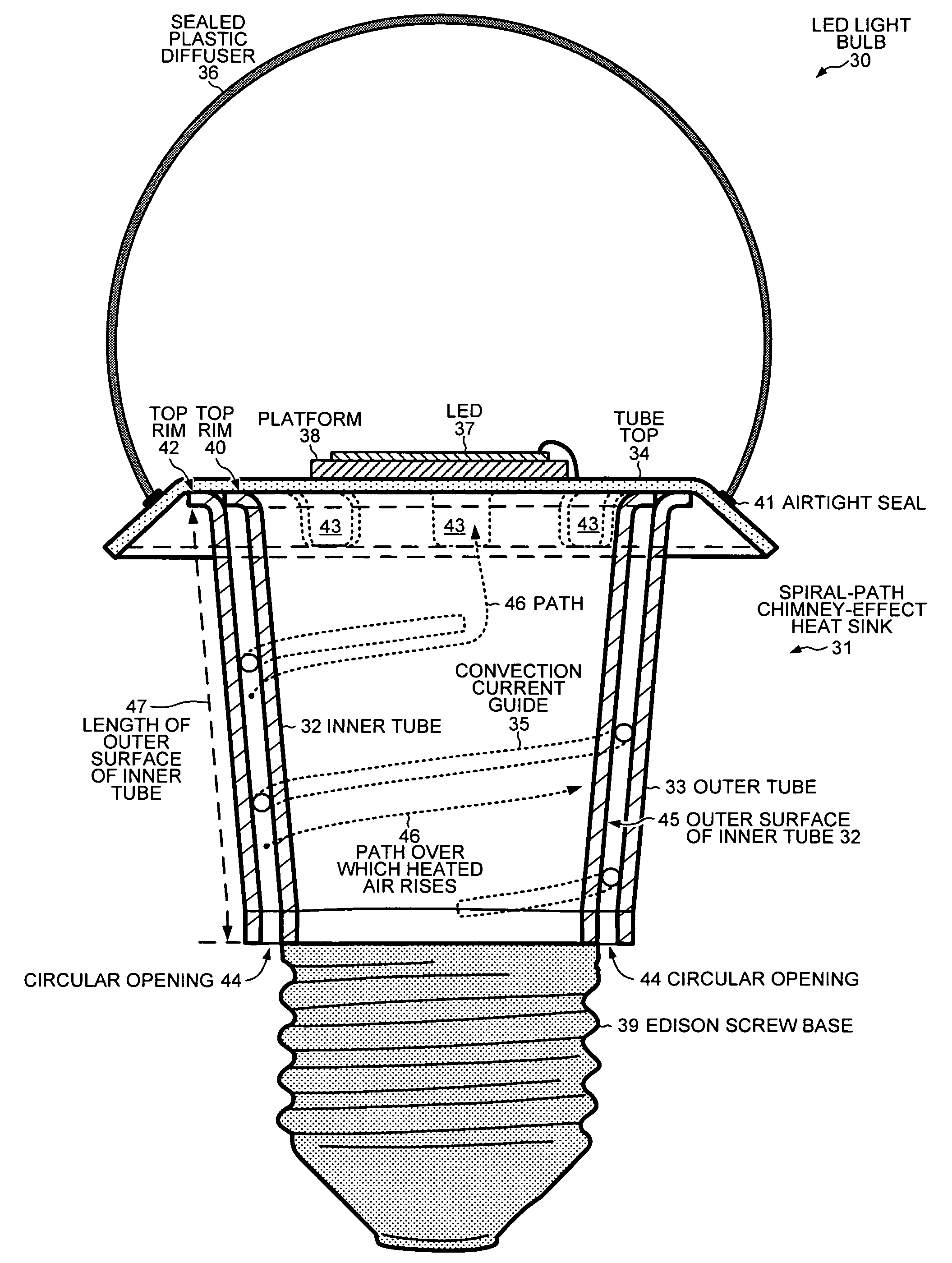
[0037]FIG. 4 is a cross sectional diagram of an LED light bulb 30 with a spiral-path chimney-effect heat sink 31. Heat sink 31 has an inner tube 32, an outer tube 33, a tube top 34 and a convection current guide 35. Inner tube 32 and outer tube 33 are coaxial, and convection current guide 35 is disposed between inner tube 32 and outer tube 33. LED light bulb 30 has the form factor of a conventional incandescent bulb. Even through no vacuum is maintained around a glowing filament, a sealed plastic diffuser 36 has the shape of a bulb and is attached to tube top 34. Instead of maintaining a vacuum, sealed plastic diffuser 36 performs the function of diffusing the light emitted from a light emitting diode (LED) 37 that is attached on top of tube top 34. LED 37 is attached to tube top 34 via a platform 38. In one embodiment, platform 38 is made o...


PUM

PropertyMeasurementUnit
pressureaaaaaaaaaa
lengthaaaaaaaaaa
thicknessaaaaaaaaaa

Abstract

A spiral-path chimney-effect heat sink cools an LED light bulb by increasing the length of the path over which heated air rises between two coaxial tubes. A tube top is attached to one end of the tubes. A light emitting diode (LED) is thermally coupled through the tube top to the inner tube. There are window openings below the rim where the outer tube attaches to the tube top. A convection current path guide is disposed between the inner and outer tubes. The convection current path guide is a spiral wire that causes rising air to follow a longer spiral path around the heated inner tube before the air exits the heat sink through the window openings. An Edison screw base is attached to the end of the inner tube opposite the end attached to the tube top. The coaxial tubes can be cylindrical tubes, conical tubes or square tubes.

Description

TECHNICAL FIELD[0001]The present invention relates generally to heat sinks and, more specifically, to improving the performance of a chimney-effect heat sink.BACKGROUND INFORMATION[0002]The demand for ever more efficient sources of light has led to a progression from incandescent lights to specialized fluorescent lights, e.g., using sodium or mercury vapor, to light emitting diodes. Light emitting diodes (LEDs) not only exhibit relatively high efficiency, but also offer a relatively uncomplicated construction and a long useful life. LEDs do, however, emit relatively large amounts of heat and require suitable heat sinks to dissipate that heat. An efficient heat sink can extend the lifespan of an LED light by preventing the LED from operating at excessively high temperatures. Heat sinks for LED lights have been fabricated by extruding them from aluminum or an aluminum alloy. The extrusion process involves pushing the heat-sink material through a die of the desired cross-section.[0003]...

Claims


Application Information

Patent Timeline
Patent Type & Authority Applications(United States)
IPC IPC(8): F28F13/00B23P15/26F28F1/00
CPCF21K9/135F21V3/00Y10T29/49391F21V29/78F21V29/83F21Y2101/02F21K9/232F21Y2115/10H01L2924/19107
Inventor MOSHTAGH, VAHID S.
Owner BRIDGELUX INC
Why Eureka
Try Eureka