

Magnetic resonance device
a magnetic resonance and device technology, applied in the direction of measurement devices, magnetic measurements, instruments, etc., can solve the problems of large motion artifacts, coherent phase variations due to object motion, and inability to generate motion artifacts, etc., to achieve high-precision measurement
- Summary
- Abstract
- Description
- Claims
- Application Information
AI Technical Summary
Benefits of technology
Problems solved by technology
Method used
Image

Examples
first embodiment
[0044]Hereafter, the first embodiment of the present invention will be explained. In all of the drawings for explaining the embodiments of the present invention, elements having the same function are indicated with the same numerals or symbols, and repetition of the explanations thereof are omitted.
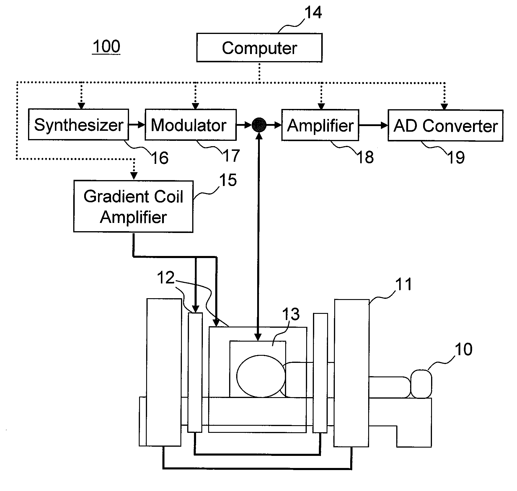
[0045]First, the device configuration of the magnetic resonance device of the present embodiment will be explained. FIG. 1 is a configurational diagram for explaining the outline of the magnetic resonance device 100 according to the present embodiment. The magnetic resonance device 100 is provided with a static magnetic field coil 11, a gradient magnetic field coil 12, a radio frequency coil 13, a computer 14, a gradient magnetic field amplifier 15, a synthesizer 16, a modulator 17, an amplifier 18, and an AD converter 19.
[0046]The synthesizer 16 generates a radio frequency wave, the modulator 17 modulates wave shape of the radio frequency wave generated by the synthesizer 16, amplifies i...
second embodiment
[0118]Hereafter, the second embodiment of the present invention will be explained. According to the present embodiment, the center frequencies of the excitation RF pulse and the inversion RF pulse to be irradiated and the center frequencies used as the reference for detection of navigator magnetic resonance signals and magnetic resonance signals for SI are separately set. The magnetic resonance device for the present embodiment is basically the same as that for the first embodiment. However, the pulse sequence for controlling operations of the devices constituting the magnetic resonance device 100 with the computer 14 is different from that of the first embodiment. Hereafter, only the configurations different from those of the first embodiment will be explained. Further, in the present embodiment, the center frequency of the pulse to be irradiated and the center frequency used as the reference for detection of signals to be received are simply referred to as center frequency of puls...
third embodiment
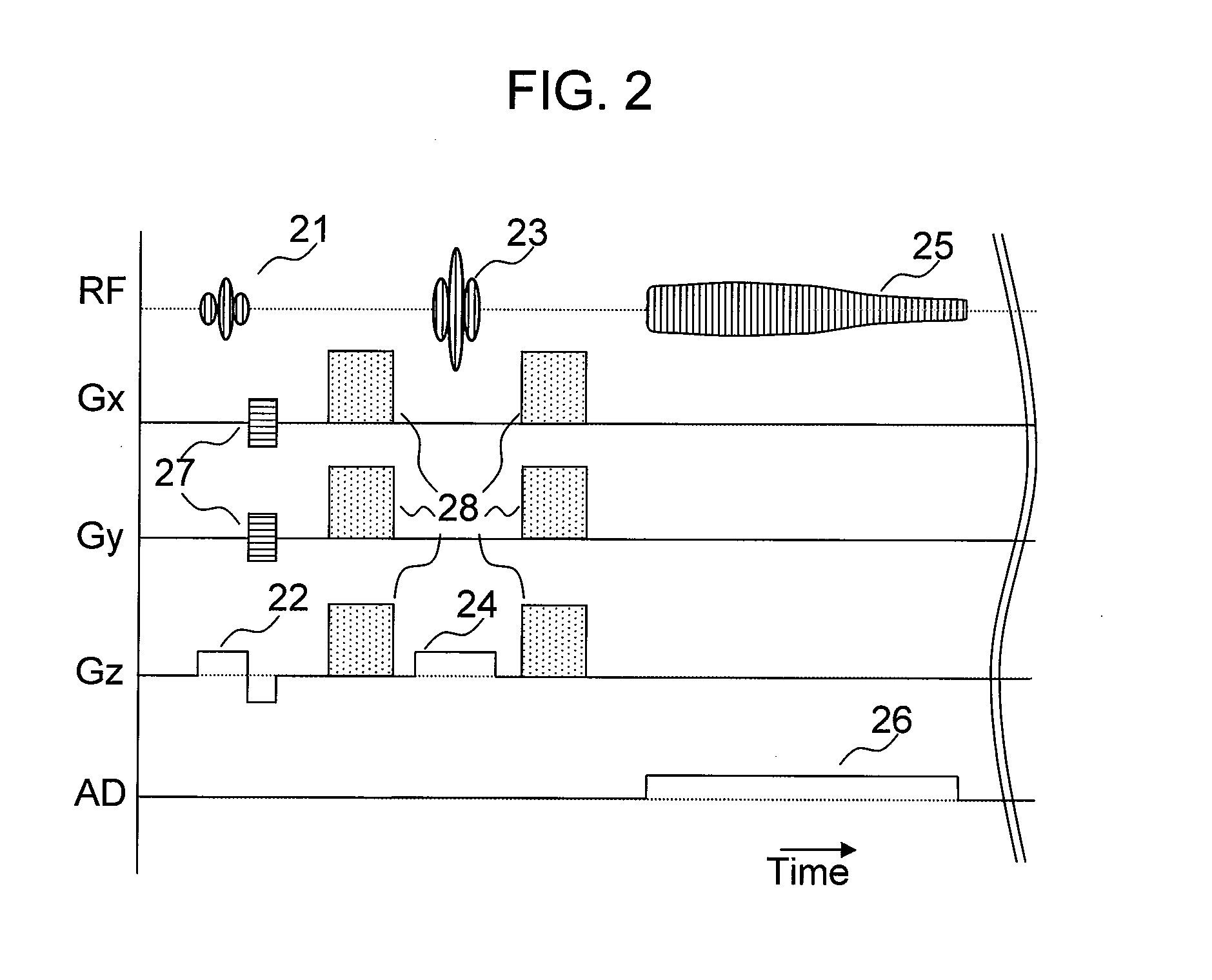
[0135]Hereafter, the third embodiment of the present invention will be explained. According to the present embodiment, prior to obtaining the magnetic resonance signal for SI, water signals are suppressed. The magnetic resonance device of the present embodiment is basically the same as that of the first embodiment. The pulse sequence according to the present embodiment for controlling operations of the devices constituting the magnetic resonance device 100 with the computer 14 is different from that of the first embodiment. Only the configurations different from those of the first embodiment will be explained below. This embodiment is typically for SI of which objective nuclide is 1H.
[0136]The pulse sequence 405 according to the present embodiment will be explained below. FIG. 15 shows a pulse sequence 405 according to the present embodiment. The pulse sequence 405 of the present embodiment is basically the same as that of the pulse sequence 401 of the first embodiment shown in FIG....
PUM
 Abstract
Description
Claims
Application Information