Micromechanical tunable fabry-perot interferometer, an intermediate product, and a method for producing the same

a technology of fabryperot interferometer and micromechanical tunable fabryperot, which is applied in the direction of instruments, optical elements, optics, etc., can solve the problems of reducing the performance of the mirror, and affecting the etching process. , to achieve the effect of reducing the density of the pinhole, and improving the etching process

Active Publication Date: 2012-03-01
TEKNOLOGIAN TUTKIMUSKESKUS VTT
View PDF3 Cites 34 Cited by
  • Summary
  • Abstract
  • Description
  • Claims
  • Application Information

AI Technical Summary

Benefits of technology

[0011]The object of the invention is achieved with a solution, in which a tunable Fabry-Perot interferometer has silicon-rich silicon nitride in at least one layer of a mirror. The use of silicon oxide in the mirror layers can thus be avoided or reduced. With this inventive solution it is possible to avoid the above mentioned problems related with the prior art.
[0026]Significant advantages can be achieved with the invention when compared to the prior known solutions. In an inventive Fabry-Perot interferometer it is not necessary to use silicon oxide layers in the mirrors. Therefore, the etching of the sacrificial layer does not deteriorate the mirror layers. It is therefore possible to provide the etching of the holes in the movable mirror after all mirror layers at the optical area have been deposited, and thus it is possible to etch at least two layers of different material, preferably all layers of the movable mirror, within the same etching phase. As the etching does not deteriorate the layers of the movable mirror it is possible to remain straight edges in the holes which are made to the movable mirror for etching the sacrificial layer. The movable mirror has thus a homogeneous structure and keeps its even form. It is also possible to include a higher density of etching holes in the movable mirror, which improves the etching process and whereby HF vapour etching can be used.
[0027]When the sacrificial layer is removed with HF vapour etching, this can be performed after cutting the chips and possibly also after encapsulating the chips. This allows simple cutting and packaging procedures because the movable mirror does not need to be released at that phase and is therefore not sensitive to environmental stress, such as changes of temperature or humidity, contamination, etc. Also, it is possible to transport the interferometers in normal transportation manners because the movable mirrors can be released after the transport.
[0028]Secondly, it is possible to allow a higher density of pinholes in the mirror layers because the etching agent is not harmful to any of the mirror layers. Therefore, it is possible to apply higher roughness at the mirror surfaces, whereby the risk of the mirrors sticking to each other is decreased. As a consequence of these advantages, higher yield can be achieved in the production of Fabry-Perot interferometers, and the high functional reliability of interferometers can be achieved.
[0029]It is further possible to determine the index of refraction by adjusting the contents of silicon in the silicon-rich silicon nitride. By adding silicon to silicon nitride the value of the index of refraction is increased compared to the pure silicon nitride. By applying silicon-rich silicon nitride wherein the value of the index refraction is closer to the corresponding value of the polycrystalline silicon layer, a same optical effect is achieved by implementing the mirror with a larger number of λ / 4 layers. This way it is possible to achieve a mirror structure which is thicker and stronger compared to, for example, structures where silicon oxide layers are used. Preferably, the silicon-rich silicon nitride of a mirror layer has such a proportion of silicon that the material has a value of the index of refraction which value is between the corresponding values of polycrystalline silicon and silicon nitride.

Problems solved by technology

However, there are some disadvantages related with the prior art solutions for production of interferometers and the interferometer components.
However, when the sacrificial layer is etched through the holes of the movable mirror the silicon oxide layers may also become etched at the edges of the holes.
However, this causes that the released mirror is not evenly thick at its all locations, and the mirror has an inhomogeneous structure.
While the mirror inevitably has a tensile stress, this will further cause bending of the mirror, which degrades the performance of the mirror.
If these layers are etched, the structure of the mirrors is deteriorated.
However, when the surfaces of the mirrors are smooth, there is an increased risk of the sticking to each other if they touch each other.
E.g. instantaneous overvoltage at the control circuit of the component or high humidity may cause the mirrors to stick permanently to each other and thus cause the component to become non-functional.
A further problem relates to removing the sacrificial layer between the mirrors.
Such a separate process increases the complicity of the production process.
As a result of these disadvantages, the yield of interferometers in the production may be low, and reliability of the produced interferometers possibly does not reach a required level.

Method used


Image

  • Micromechanical tunable fabry-perot interferometer, an intermediate product, and a method for producing the same
  • Micromechanical tunable fabry-perot interferometer, an intermediate product, and a method for producing the same
  • Micromechanical tunable fabry-perot interferometer, an intermediate product, and a method for producing the same

Examples


Embodiment Construction

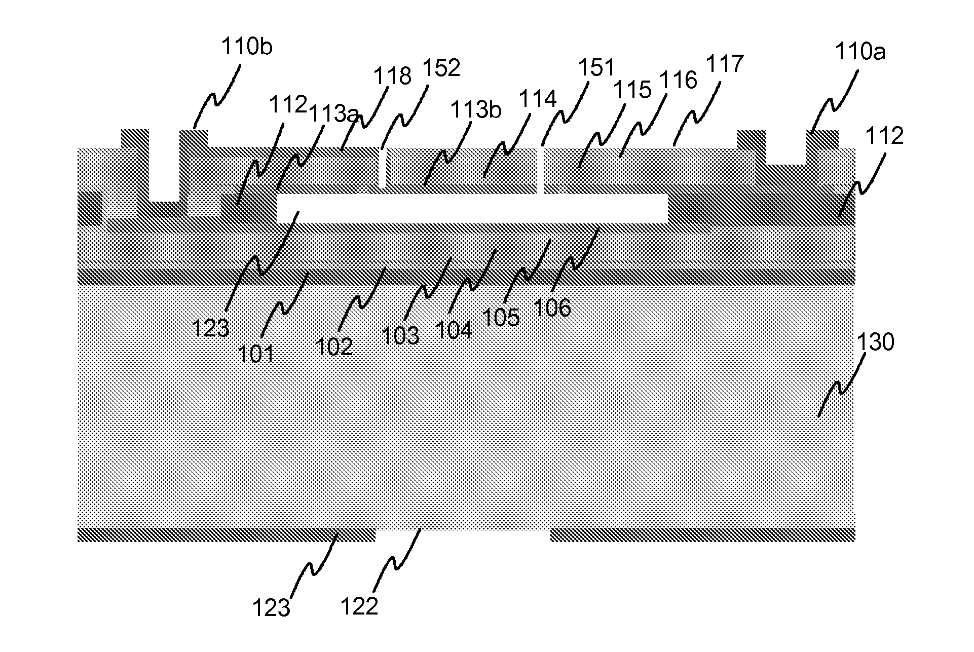
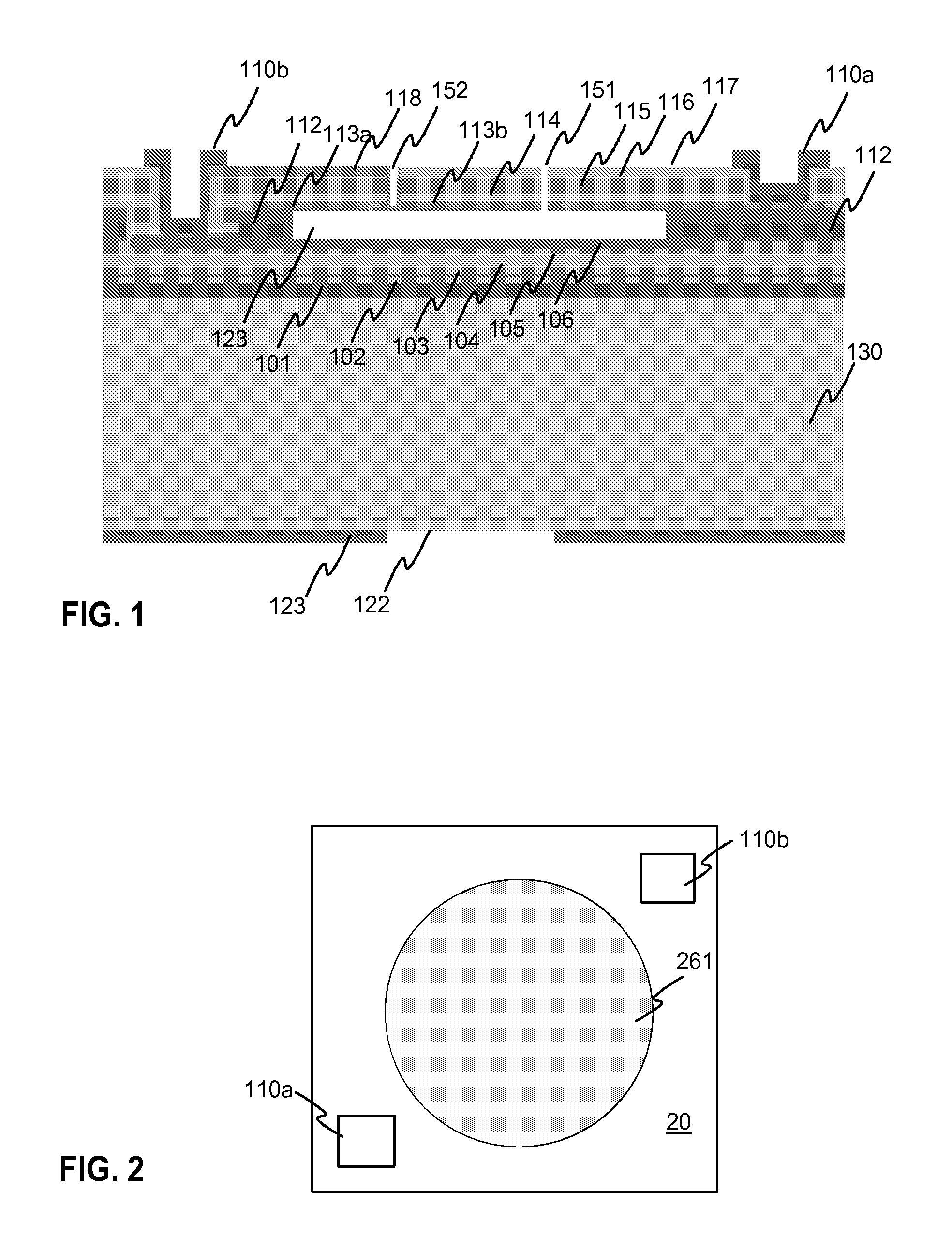
[0041]FIG. 1 illustrates a cross section of an exemplary Fabry-Perot interferometer according to the invention. The interferometer has a substrate 130 of e.g. monocrystalline silicon material, on which there is an optical matching layer 101 of e.g. silicon oxide. The reflecting layers of the fixed mirror are provided by layers 102-105, wherein layers 102 and 104 are of polycrystalline silicon, and layers 103 and 105 are of silicon-rich silicon nitride. Patterned layer 106 is made of doped polycrystalline silicon and serves as a control electrode of the fixed mirror.

[0042]The interferometer has a second, movable mirror which has reflecting layers 114-117. Layers 115 and 117 are of polycrystalline silicon, and layers 114 and 116 are of silicon-rich silicon nitride. Layer 113a, 113b is made of doped polycrystalline silicon and serves as electrically conducting control electrodes of the fixed mirror.

[0043]The electrode 106 of the lower, fixed mirror is electrically connected to the conn...


PUM


Abstract

The invention relates to controllable Fabry-Perot interferometers which are produced with micromechanical (MEMS) technology. Producing prior art interferometers includes a risk of deterioration of mirrors during the etching of the sacrificial layer (123). According to the solution according to the invention at least one layer (103, 105, 114, 116) of the mirrors is made of silicon-rich silicon nitride. In the inventive Fabry-Perot interferometer it is possible to avoid or reduce using silicon oxide in the mirror layers whereby the risk of deterioration of the mirrors is reduced. It is also possible to use mirror surfaces with higher roughness, whereby the risk of the mirrors sticking to each other is reduced.

Description

TECHNICAL FIELD[0001]The invention relates to a Fabry-Perot interferometer and a method for producing a Fabry-Perot interferometer. More specifically, the invention relates to tunable Fabry-Perot interferometers which are produced with micromechanical (MEMS) technology. The technical field of the invention is specified in the preamble of the independent claims.BACKGROUND TECHNOLOGY[0002]Fabry-Perot interferometers are used as optical filters and in spectroscopic sensors, for example. A Fabry-Perot interferometer is based on parallel mirrors, whereby a Fabry-Perot cavity is formed into a gap between the mirrors. The pass band wavelength of a Fabry-Perot interferometer can be controlled by adjusting the distance between the mirrors i.e. the width of the gap. It is common to use micromechanical technology for producing Fabry-Perot interferometers. Such a solution is described e.g. in patent document FI95838.[0003]Prior art structure of a micromechanical interferometer usually includes ...

Claims


Application Information

Patent Timeline
Patent Type & Authority Applications(United States)
IPC IPC(8): G01B9/02H01L21/02
CPCB81B3/0013B81B2201/042G02B26/001G01J3/26B81C2201/115G02B5/284
Inventor BLOMBERG, MARTTI
Owner TEKNOLOGIAN TUTKIMUSKESKUS VTT
Why Eureka
Try Eureka