Cooling syngas via reaction of methane or light hydrocarbons with water

a technology of methane or light hydrocarbons and syngas, which is applied in the direction of combustible gas catalytic treatment, combustible gas production, pressurized chemical process, etc., can solve the problems of downtime in commercial gasification systems, achieve more efficient syngas generation, avoid ash-handling problems, and reduce downtime

Active Publication Date: 2017-04-25
ENERGY & ENVIRONMENTAL RES CENT FOUNDATIO
View PDF6 Cites 0 Cited by
  • Summary
  • Abstract
  • Description
  • Claims
  • Application Information

AI Technical Summary

Benefits of technology

[0005]In various embodiments, the methane or light hydrocarbon quench of the present invention can be used to supplement or replace heat exchange-type syngas coolers. Heat exchange-type syngas coolers have significant ash-handling issues which has led to downtime in commercial gasification systems. In various embodiments, the present invention can avoid ash-handling issues, decreasing downtime and providing more efficient syngas generation. Heat exchange-type syngas coolers use high-temperature materials and metallic heat exchange tubes to exchange the heat in the syngas to produce steam. In various embodiments, the present invention can avoid the need for utilization of expensive high-temperature materials. In various embodiments, the present invention can avoid or reduce the use of metallic heat exchange surfaces.
[0006]In various embodiments, the methane or light hydrocarbon quench of the present invention can be used to supplement or replace a direct water quench. Direct water quenching designs waste thermal energy. In various embodiments, in contrast to direct water quenching designs, using methane, light hydrocarbons, methane-containing gases, or light hydrocarbon-containing gases as a quench medium to cool the syngas via endothermic reaction of the methane or light hydrocarbons with water allows for recovery of the thermal energy in the syngas in the form of additional syngas production via the carbon monoxide and hydrogen generated from the reaction of the methane or light hydrocarbons and water (e.g. steam methane or light hydrocarbon reforming). In various embodiments, the methane or light hydrocarbon quench of the present invention can be combined with other processes that generate methane or light hydrocarbons, such as a Fischer-Tropsch process, such that the methane or light hydrocarbons generated can be recycled back to the quench section for cooling and additional syngas production. In various embodiments, the methane or light hydrocarbon quench of the present invention can destroy or reduce the concentration of organics heavier than methane or light hydrocarbons, which can prevent or reduce coking during later catalytic reforming processes.
[0007]In various embodiments, the methane or light hydrocarbon quench of the present invention can increase the hydrogen to carbon monoxide ratio of the syngas, which can improve the quality of the syngas for formation of liquid fuels, ammonia, and hydrogen production. In various embodiments, the methane or light hydrocarbon quench of the present invention can decrease the carbon dioxide concentration of the syngas via better integrated thermal efficiency and via a higher hydrogen to carbon monoxide ratio.
[0008]In various embodiments, a wide variety of methane-containing or light hydrocarbon-containing gases can be used to perform the methane or light hydrocarbon quench of the present invention, such as natural gas, such as pipeline quality gas, or shale gas, stranded natural gases, unprocessed natural gases. In various embodiments, the methane or light hydrocarbon quench of the present invention can operate in the presence of high levels of sulfur and particles, such as in the hot syngas, in the methane, or in the light hydrocarbon feed source. In various embodiments, performing the quench with natural gas can provide reforming of the natural gas without pretreatment to remove or decrease the concentration of sulfur. In various embodiments, the methane or light hydrocarbon quench can be performed upstream, downstream, or a combination thereof, of slag removal. In various embodiments, a Joule-Thompson separation can be used to inject heavier components of shale gas in the gasifier and the lighter components in the downstream catalytic reactor, enabling reforming of substantially all components.
[0009]In various embodiments, the methane or light hydrocarbon quench of the present invention can operate without the addition of extra water or steam to the hot syngas. In various embodiments, water or steam can be added to the hot syngas to facilitate the endothermic reaction between the methane or light hydrocarbons and water in the syngas. In various embodiments, steam from other sections of the process, including low-grade steam, can be recycled for use as additional water in the hot syngas. In various embodiments, incorporation of recycled low-grade steam can avoid heat of vaporization energy penalties associated with other means of disposing of the steam.
[0010]In various embodiments, the methane or light hydrocarbon quench of the present invention can avoid the formation of additional tar species, which are generally considered undesirable in gasification processes.

Problems solved by technology

Heat exchange-type syngas coolers have significant ash-handling issues which has led to downtime in commercial gasification systems.

Method used


Image

  • Cooling syngas via reaction of methane or light hydrocarbons with water
  • Cooling syngas via reaction of methane or light hydrocarbons with water
  • Cooling syngas via reaction of methane or light hydrocarbons with water

Examples


example 1

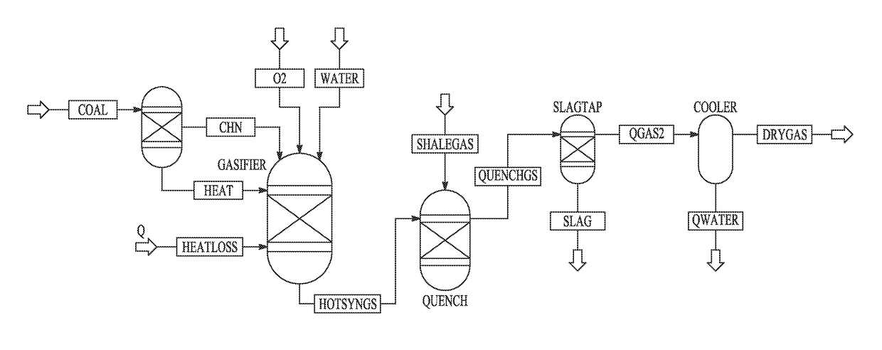
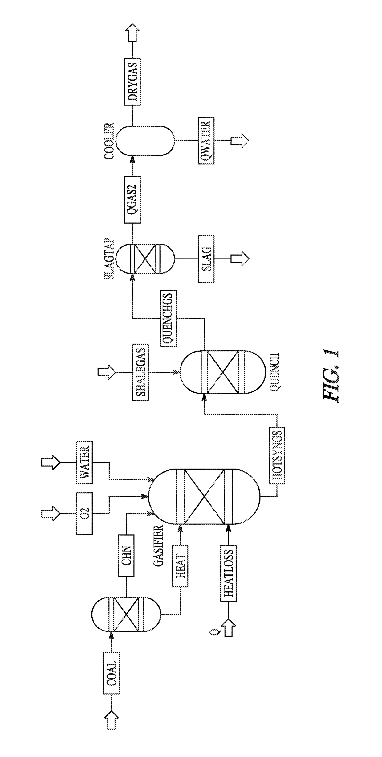
[0045]Aspen Plus® software was used to model the reaction of syngas with pipeline quality methane and shale gas to determine the amount of cooling that is feasible without having excess introduction of hydrocarbons into the gas stream. Tampa Electric's Polk Power Station integrated gasification combined cycle (IGCC) facility was used as the modeling basis for this study. A model was built in Aspen Plus that represents a simplified entrained-flow gasifier and quench system, illustrated in FIG. 1. No catalytic influences were considered in this model.

[0046]General Conditions.

[0047]The fuel feed rate, oxygen flow rate, and water feed rate were determined according to published operational estimates at the Polk Power Station IGCC. The facility is a 250-MW net power station, with a nominal coal feed rate of 2200 tons / day, oxygen feed rate of 2171 tons / day, and slurry water feed rate of 972 tons / day. Pittsburgh No. 8 was used as the coal for the study. The exit temperature was also set ba...

example 2

[0053]Using Aspen Plus® software, a computer model was designed. Inputs from a commercial GE gasifier at Tampa Electric's Polk Power Station integrated gasification combined cycle (IGCC) facility were used to model the syngas quality at the entrance of the quench section. FIG. 6 illustrates the results, and shows the level of cooling that can be achieved utilizing methane with and without catalytic influences. The data are presented as a weight ratio of the methane input compared to the coal feed rate in the gasifier. In the noncatalytic case, the steam methane reforming reactions are driven forward to achieve temperatures of approximately 1950° F. After this point, additional cooling achieved is almost exclusively from the heat capacity of the methane. In the catalytic case, cooling below 1200° F. is achieved with a methane to coal ratio of about 0.22. Simplified assumptions were used in this modeling effort, in line with the General Conditions of Example 1.

[0054]The terms and expr...


PUM

PropertyMeasurementUnit
temperatureaaaaaaaaaa

Abstract

Various embodiments disclosed relate to cooling shale gas via reaction of methane, light hydrocarbons, or a combination thereof, with water. In various embodiments, the present invention provides a method of cooling syngas. The method includes contacting the hot syngas with methane or light hydrocarbons. The hot syngas includes water and has a temperature of about 800° C. to about 3000° C. The contacting is effective to endothermically react the methane or light hydrocarbons with the water in the hot syngas to form carbon monoxide and hydrogen and to provide a cooled syngas having a lower temperature than the hot syngas.

Description

CROSS-REFERENCE TO RELATED APPLICATION[0001]This application claims the benefit of priority to U.S. Provisional Patent Application Ser. No. 62 / 181,291 filed Jun. 18, 2015, the disclosure of which is incorporated herein in its entirety by reference.BACKGROUND[0002]Many of the high-temperature gasification system vendors today offer two design choices: direct water quenching or heat exchange-type syngas cooling. Direct quenching provides a reliable design from an operations standpoint with minimal downtime, but all of the heat contained in the syngas is lost, and a significant energy penalty is realized. Syngas coolers allow for heat recovery and increased efficiency. However, ash-plugging problems in syngas coolers have led to significant amounts of downtime of commercial gasification units, and much research has been attempted to solve these issues. Due to operational concerns such as ash-plugging in the cooler, many gasification facilities elect to take the energy penalty and direc...

Claims


Application Information

Patent Timeline
Patent Type & Authority Patents(United States)
IPC IPC(8): B01J8/06B01J8/00B01J3/00C01B3/34C10J3/82
CPCC01B3/34C10J3/82C01B2203/0877C10J2300/093C10J2300/0916C10J2300/0946C10J2300/0959C10J2300/0976C10J2300/1846C10J2300/1853C01B3/38C10K1/06C10K3/04C01B2203/1241C01B2203/1247C10J2300/1884C10J2300/0913C01B2203/0233C01B2203/06C01B2203/1052C01B2203/1058C01B2203/1064C01B2203/107C01B2203/1076Y02E20/16Y02E20/18C10G2300/1022Y02P20/145
Inventor STANISLOWSKI, JOSHUA J.HOLMES, MICHAEL J.SWANSON, MICHAEL L.
Owner ENERGY & ENVIRONMENTAL RES CENT FOUNDATIO
Why Eureka
Try Eureka