

Spring clip method for Anti-rotation and thrust constraint of a rolling element bearing cartridge
- Summary
- Abstract
- Description
- Claims
- Application Information
AI Technical Summary
Benefits of technology
Problems solved by technology
Method used
Image


Examples
first embodiment
[0046]the dual mode snap ring (102), as shown in FIGS. 8A and 8B, has a radially inside surface (112) and a radially outside surface (111). In addition to the features of a conventional snap ring, the dual mode snap ring (102) has one or more non-round, e.g., flat sections or shapes generally providing rotational constraint (107), fabricated into the generally round or circular inside surface (112) of the ring such that, with the dual mode snap ring in the relaxed state, the flat sections (107) in the dual mode snap ring fit to corresponding flat inner sections (106) of grooves (94), fabricated into the REB cartridge, or outer race.
[0047]On the radially outer surface (111) the dual mode snap ring (102) of the first embodiment has a male tab (104), projecting radially outward, which fits into a reverse imaged scallop (103) in the bearing housing to prevent rotation of the snap ring with respect to the bearing housing. This rotationally arresting arrangement of dual mode snap ring to ...
second embodiment
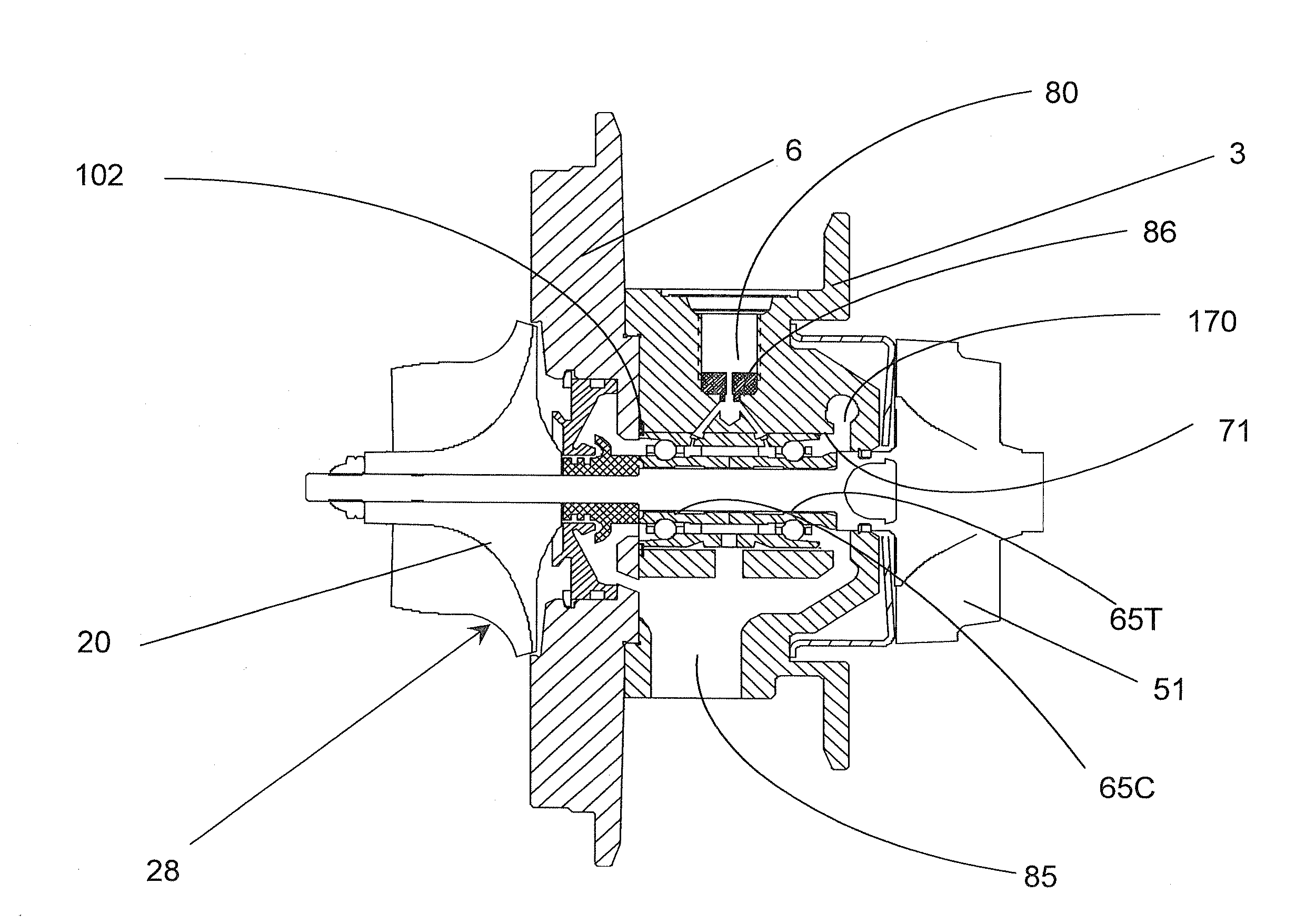
[0063]In the invention, a dual mode snap ring (102) resides in a snap ring groove (95) in the bearing housing (3). As seen in FIGS. 8, 13, and 14, the snap ring groove has a turbine-housing side (67) and a compressor-side (168). There exists a snap ring groove (94) in the outer surface (172) of the outer race or cartridge (64).
[0064]In the first embodiment of the invention, the rotational constraint of the dual mode snap ring employed a protruding male tab (104) which fit into a reverse-imaged recess (103) in a “lock and key” manner. The tab and recess were situated in either of the bearing housing (3) or the bearing housing closure (6). In the second embodiment of the invention, the constraint, both axially and rotationally, of the REB cartridge is provided by a dual mode snap ring and the bearing housing only.
[0065]Since the snap ring groove is contained wholly within the bearing housing, the anti-rotation feature recess must be machined “blind” to intersect the cheek faces (67 an...
PUM
 Abstract
Description
Claims
Application Information