
Wireless Communication System, Base Station Device, and Program

Inactive Publication Date: 2012-03-01
KDDI CORP
View PDF0 Cites 56 Cited by
  • Summary
  • Abstract
  • Description
  • Claims
  • Application Information

AI Technical Summary

Benefits of technology

[0062]It is an object of the present invention to provide a wireless communication system, a base station device, and a program, which prevent a non-connection-permitted terminal device, approaching a predetermined base station device, from interfering with the base station due to failure of handoff, wherein it is possible to reduce interference affecting a control signal forwarded to the non-connection-permitted terminal device from another base station device.
[0090]The present invention is able to reduce bandwidths of already allocated radio resources irrespective of tightness of radio resources, thus producing a vacancy of radio resources. This makes it possible to allocate an appropriate combination of radio resources to a mobile terminal device newly connected with the base station device, ensuring transmission of sounding reference signals (SRS). Thus, it is possible to implement frequency scheduling reflecting frequency characteristics of a newly connected mobile terminal device, thus improving throughputs of mobile terminal devices and communication capacity of the OFDMA system.

Problems solved by technology

In this case, the non-CGS terminal device fails to conduct handoff from the macro-base station device to the CSG base station device, so that the non-CSG terminal device will intensely interfere with radio waves emitted from the CSG base station device.
For this reason, when the non-CSG terminal device intensely interferes with the CSG base station device, the non-CSG terminal device may be unable to demodulate PDCCH packets transmitted thereto from the macro-base station device.
Additionally, the non-CSG terminal device may be unable to demodulate traffic channels allocated to the PDSCH region.
This situation leads to a communication breakdown with the non-CSG terminal device.
CSG base stations are used to expand communication areas, whereas CSG base stations may intensely interfere with non-CSG terminal devices (which are not registered with CSG base stations but located in coverage areas of CSG base stations) so as to degrade their reception power of physical control channels.
When an unregistered terminal device (e.g. a non-CSG terminal device) is located in the coverage area of a small-scale base station (e.g. a CSG base station) facilitating communication with a registered terminal device (e.g. a CSG terminal device), there is a problem in that reception quality of a physical control channel of the unregistered terminal device must be degraded due to intense interference with the small-scale base station.
Specifically, the following problems occur in connection with RS, PCFICH, PDCCCH radio resources.
When a non-CSG terminal device, which is not permitted to access a CSG base station, approaches the CSG base station, the non-CSG terminal device is unable to perform RS reception with a macro-base station due to intense interference with the CSG base station.
This may lead to frequent occurrence of radio link failure.
When a non-CSG terminal approaches a CSG base station, the non-CSG terminal device is unable to perform PCFICH reception with a macro-base station due to intense interference with the CSG base station.
When a non-CSG terminal device approaches a CSG base station, the non-CSG terminal device is unable to perform PDCCH reception with a macro-base station due to intense interference with the CSG base station.
In the uplink communication from a mobile terminal device to a base station device, the base station device is unable to obtain communication quality of other frequency resources other than frequency resources which the base station device receives from the mobile terminal device if frequency resources which the base station device allocates to the mobile terminal device do not constitute the entire frequency range of the wireless communication system.
However, Non-Patent Document 1 reveals a certain limitation in radio resources used for transmitting sounding reference signals (SRS) (hereinafter, referred to as SRS radio resources), whereby mobile terminal devices interfere with each other when all mobile terminal devices normally transmit sounding reference signals (SRS) so that mobile terminal devices cannot properly demodulate sounding reference signals (SRS); hence, it is difficult to obtain frequency characteristics.
Due to tightness of SRS radio resources, it becomes very difficult to allocate SRS radio resources to mobile terminal devices newly visiting cells since the increasing number of mobile terminal devices has currently visited cells.
Unless SRS radio resources are allocated to mobile terminal devices, it is impossible to measure frequency characteristics of mobile terminal devices.
This prevents frequency scheduling, which is an important feature of the OFDMA system, and increases probability of causing degradation of throughput.
As a result, the conventional technologies are unable to demonstrate adequate communication quality in mobile terminal devices unless SRS radio resources are appropriately allocated to mobile terminal devices newly connected to base station devices due to tightness of SRS radio resources.

Method used


Image

  • Wireless Communication System, Base Station Device, and Program
  • Wireless Communication System, Base Station Device, and Program
  • Wireless Communication System, Base Station Device, and Program

Examples


first embodiment

1. First Embodiment

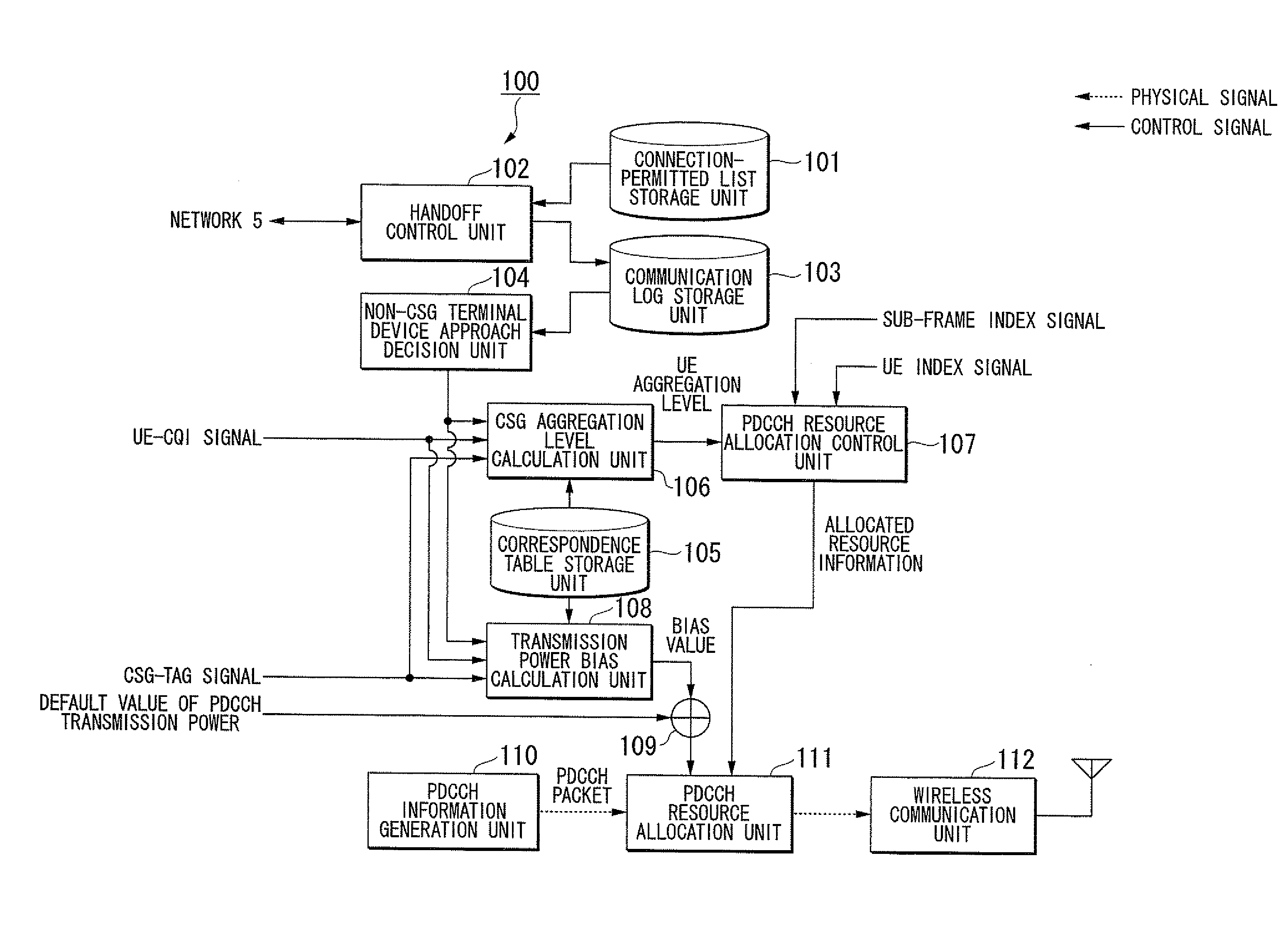
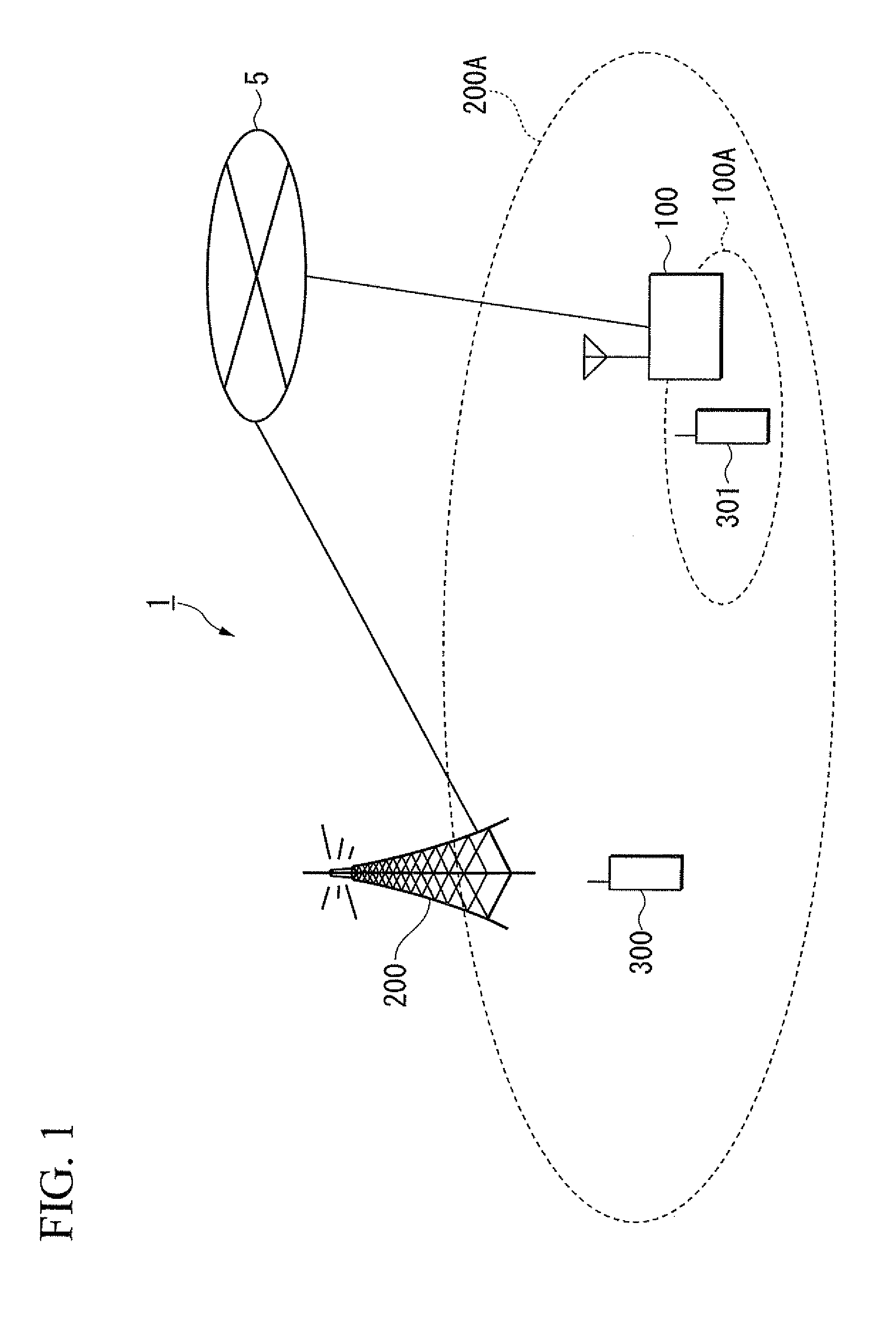
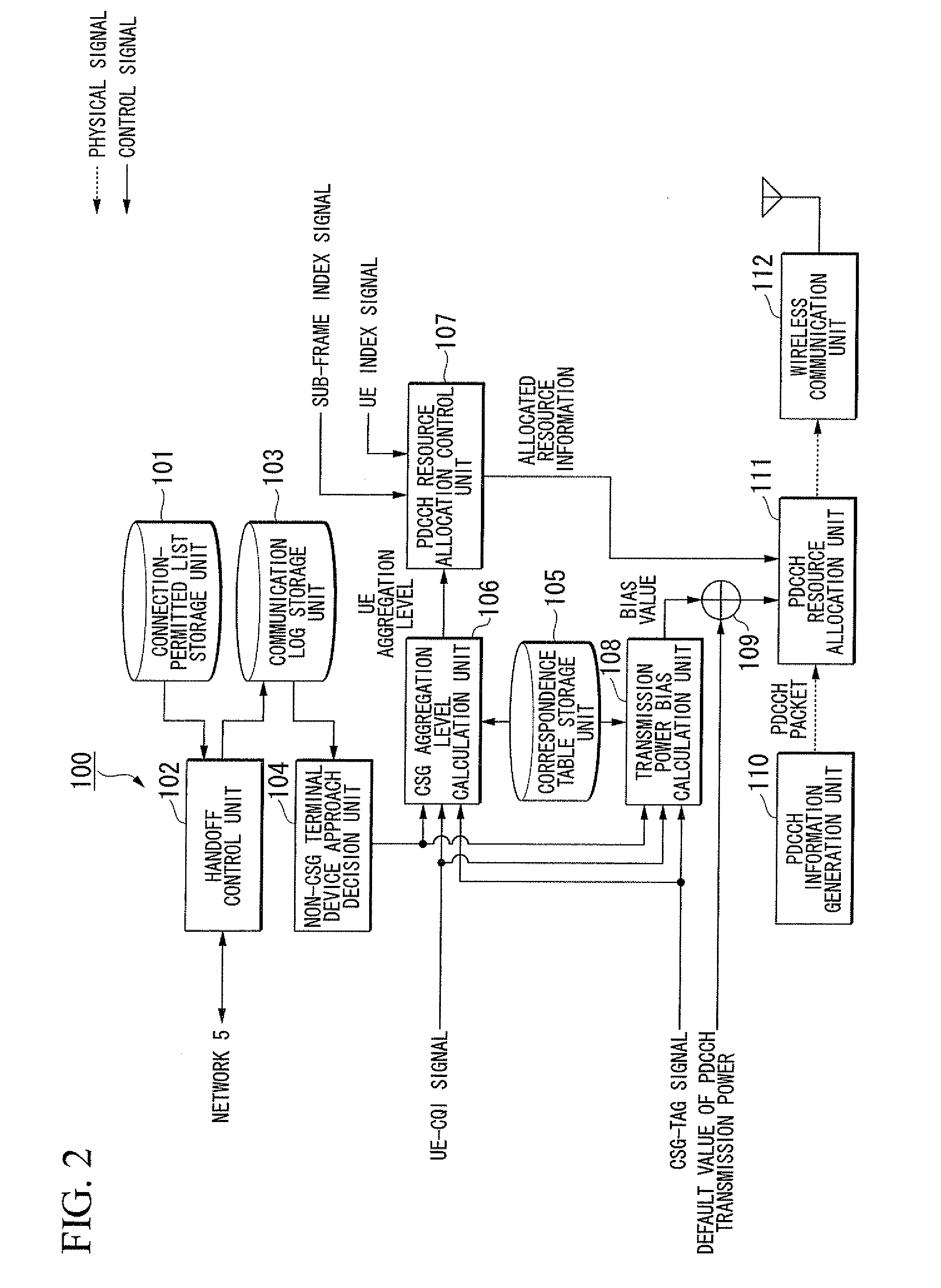
[0119]FIG. 1 is a schematic diagram of a wireless communication system 1 according to a first embodiment of the present invention. The wireless communication system 1 conducts communication according to a communication system prescribed by the LTE standard. The wireless communication system 1 includes a non-CSG terminal device 300 (where “CSG” stands for “Closed Subscriber Group”), a CSG terminal device 301, a macro-base station device 200 which conducts communication with the non-CSG terminal device 300 and the CSG terminal device 301 via communication links, a CSG base station device 100 which communicates with the CSG terminal device 301, and a network 5 which connects the CSG base station device 100 and the macro-base station device 200 via wires.

[0120]The CSG base station device 100 and the macro-base station device 200 cover communication areas 100A and 200A encompassed using broken lines. The CSG base station device 100 is located inside the communication a...

second embodiment

2. Second Embodiment

[0186]FIG. 10 is a block diagram of a CSG base station device 1010 according to a second embodiment of the present invention. FIG. 11 is a schematic diagram of a wireless communication system including the CSG base station device 1010, a macro-base station device 1020, and a non-CSG terminal device 1030. In this connection, the term “CSG base station device” is equivalent to a CSG base station, and the term “macro-base station device” is equivalent to a macro-base station.

[0187]As shown in FIG. 10, the CSG base station device 1010 includes a non-CSG terminal device detector 1110 (serving as an unregistered terminal device existence decision unit), an antenna transmission mode determination unit 1120, a scheduler mode determination unit 1130, an OFDM symbol determination unit 1140, an RS generation unit 1150, a downlink / uplink data channel allocation unit 1160, a downlink control channel allocation unit 1162, a PDCCH generation unit 1164, a data channel generation...

third embodiment

3. Third Embodiment

[0241]FIG. 15 is a block diagram of an OFDMA system according to a third embodiment of the present invention, wherein a base station device 2001 includes an SRS (Sounding Reference Signal) transmission scheduling unit 2002, an SRS radio resource notification unit 2003, and an SRS band dividing unit 2005.

[0242]The SRS transmission scheduling unit 2002 allocates radio resources, used for uplink SRS transmission, to mobile terminal devices 2004 which visit the coverage area of the base station device 2001. The SRS radio resource notification unit 2003 notifies the mobile terminal devices 2004 of SRS transmission radio resources. The SRS band dividing unit 2005 divides already allocated SRS radio resources so as to secure vacancy of SRS radio resources when no surplus SRS radio resources remain when mobile terminal devices 2004 need SRS radio resources newly allocated thereto.

[0243]FIG. 16 is an illustration of a partial configuration of uplink radio resources in the ...


PUM


Abstract

A wireless communication system includes a macro-base station device and a CGS base station device normally connected to a CSG terminal device. When a non-CGS terminal device approaches the CGS base station device, the CGS base station device reduces a frequency band for transmitting packets to the CGS terminal device so as to reduce interference with the non-CGS terminal device while increasing transmission power to the CGS terminal device so as to compensate for degradation of radio quality due to a reduction of the frequency band. Based on existence or nonexistence of a non-CSG terminal device in the coverage area, the CSG base station device selects an appropriate antenna transmission mode and an appropriate scheduler mode while setting the number of OFDM symbols utilized by a physical control channel in notifying radio resource allocation information.

Description

BACKGROUND OF THE INVENTION[0001]1. Field of the Invention[0002]The present invention relates to wireless communication systems, base station devices, and programs implementing wireless communication methods and radio resource allocation methods.[0003]The present application claims priority on Japanese Patent Application Nos. 2010-192866 (filed Aug. 30, 2010), 2010-216758 (filed Sep. 28, 2010), and 2010-219160 (filed Sep. 29, 2010), the entire content of which is incorporated herein by reference.[0004]2. Description of the Related Art[0005]Wireless interface standardization organizations, e.g. 3GPP (3rd Generation Partnership Project), have aimed to further improve frequency availability in 3rd generation wireless communication systems, e.g. W-CDMA (Wideband Code Division Multiple Access) and have been working on the standardization of successors to 3rd generation wireless communication systems, e.g. an LTE (Long Term Evolution) standard. The LTE standard adopts an OFDMA (Orthogonal...

Claims


Application Information

Patent Timeline
IPC IPC(8): H04W72/08H04W36/32
CPCH04W28/04H04W28/06H04W52/226H04W52/241H04W52/244H04L1/0026H04W72/042H04W72/0453H04W72/08H04W88/08H04W52/325H04W72/54H04W72/23
Inventor WANG, XIAOQIUKONISHIMIYAZAKI, NORIAKI
Owner KDDI CORP
Features
  • Generate Ideas
  • Intellectual Property
  • Life Sciences
  • Materials
  • Tech Scout
  • Unparalleled Data Quality
  • Higher Quality Content
  • 60% Fewer Hallucinations
Learn More