Offset Cup Impactor With a Grasping Plate for Double Mobility Implants

a technology of acetabular implants and impactors, which is applied in the field of surgical inserters, can solve the problems of difficult cleaning, difficult control, and difficult cleaning of complicated mechanical devices, and achieve the effects of reducing the possibility of cup damage, minimizing stress, and reducing the possibility of implantation procedur

a technology of acetabular implants and impactors, which is applied in the field of surgical inserters, can solve the problems of difficult cleaning, difficult control, and difficult cleaning of complicated mechanical devices, and achieve the effects of reducing the possibility of cup damage, minimizing stress, and reducing the possibility of implantation procedur

US20120053592A1Active Publication Date: 2012-03-01VIANT AS&O HLDG LLC

Image

  • Offset Cup Impactor With a Grasping Plate for Double Mobility Implants
  • Offset Cup Impactor With a Grasping Plate for Double Mobility Implants
  • Offset Cup Impactor With a Grasping Plate for Double Mobility Implants

Examples


Embodiment Construction

)

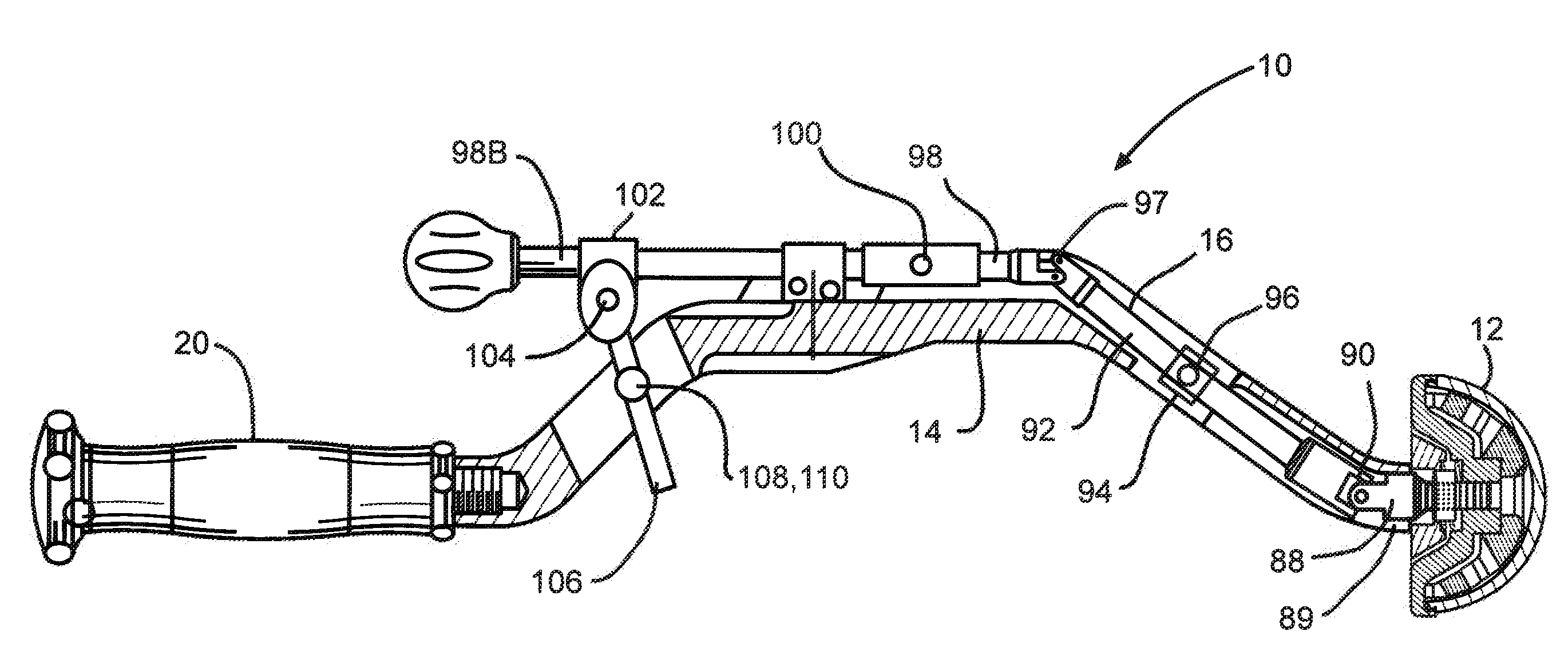
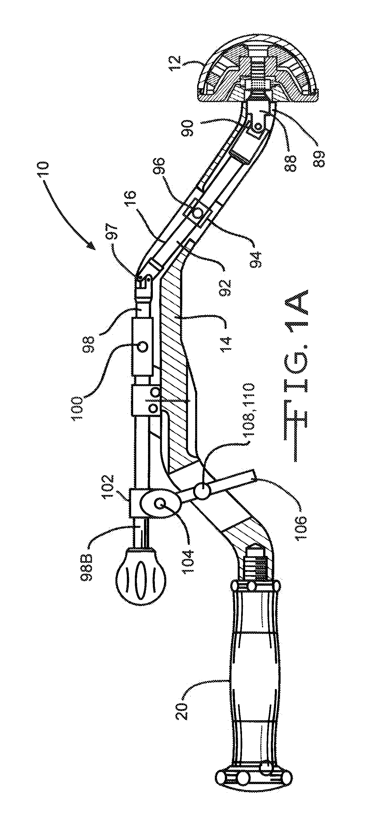
[0024]Referring now to FIGS. 1A-9, an acetabular inserter 10 is provided to aid the surgeon in controlling installation of an acetabular cup prosthesis 12. The inserter 10 has a housing 14 which encloses a drive train 16 having, at a distal end, a prosthesis engaging subassembly 18, and at the proximal end, a handle 20 which facilitates moving of the drive train by the operator. The housing 14 may be C-shaped, as shown, in order to minimize invasiveness of the surgery by better clearing anatomical structures and tissue.

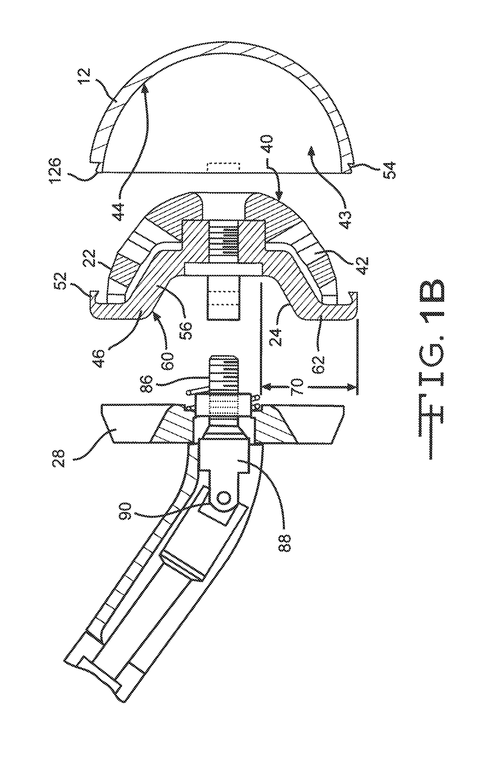
[0025]The prosthesis engaging subassembly 18, as illustrated in FIGS. 2 and 3, comprises a nose 22, a grasping plate 24, a spring 26, and an impaction plate 28 that are in direct communication with each other. The grasping plate 24 is positioned between the impaction plate 28 and the nose 22. The spring 26 is further positioned between the impaction plate 28 and the grasping plate 24 of the subassembly 18. Respective axial through-bores 30, 32, 34 extend parallel lon...


PUM


Abstract

An orthopaedic prosthetic inserter used for the implantation of double mobility cup implants is described. The inserter consists of a drive train, a C-shaped housing, and a prosthetic cup engaging subassembly. The subassembly comprises an impaction plate, a grasping plate and a domed nose. When activated by the drive train, a plurality of hook ends extending from the grasping plate latch onto the cup of the prosthetic to hold and manipulate the prosthetic cup during implantation.

Description

CROSS REFERENCE TO RELATED APPLICATIONS[0001]This application claims priority to U.S. provisional application Ser. No. 61 / 377,701, filed on Aug. 27, 2010.FIELD OF THE INVENTION[0002]This invention relates to surgical inserters for aiding in installing orthopedic prostheses, and more specifically, to an improved grasping mechanism for installing acetabular implants in the acetabular socket.BACKGROUND OF THE INVENTION[0003]A double mobility prosthetic cup is a type of acetabular implant that is designed to increase a patient's range of hip mobility. Unlike other types of acetabular implants, double mobility prosthetic cups do not have an opening through the cup portion which allows for easy manipulation during implantation. For example, a rod is typically threaded through the cup opening to the apex of the cup dome where there is typically a threaded hole. This rod is used like a handle with which to control and guide the implant during implantation. Double mobility implants, on the o...

Claims


Application Information

Patent Timeline
01 Mar 2012
Publication
US20120053592A1
IPC
A61B17/56
CPC
A61F2/4609; A61F2002/30426; A61F2002/3208; A61F2002/30565; A61F2002/305
Inventors
BURGI, JONAS