Distillation Urine Recycling Systems and Methods

a technology of urine recycling and distillation, applied in vacuum distillation separation, separation processes, filtration treatment, etc., can solve the problems of high cost of waterless urinals, low-density sealants, and constant need for potable water,

Inactive Publication Date: 2012-03-08
LIQUIDBREAKER
View PDF13 Cites 11 Cited by
  • Summary
  • Abstract
  • Description
  • Claims
  • Application Information

AI Technical Summary

Benefits of technology

[0013]The wastewater processing system can produce a concentrated effluent that can be sent to a drain pipe or collected in a user-removable tank. Collecting the concentrated effluent advantageously allows the effluent to be removed from the system and processed, such that minerals and pharmaceuticals that are present in the effluent can be extracted.

Problems solved by technology

Traditional urinals, toilets, and other urine receptacles utilize potable water to flush restroom fixtures, which amounts annually to significant quantities of water that could otherwise be consumed for drinking or other uses.
This constant need for potable water can be problematic, especially in areas with limited or no access to water.
These low-density sealants are problematic because they remain open to the atmosphere, which allows odors to permeate from the drain as the sealant is depleted.
These cartridges also require periodic replacement, which can add significantly to the waterless urinals' cost, especially in high traffic areas.
However, such valved systems typically retain a small amount of fluid in the valves after each use, which can cause odors to emanate from the valves.
In addition, the valves are generally prone to freezing in cold regions, and sticking In addition, the systems generally utilize only a single valve, which can be problematic if the valve is stuck open due to sticking, freezing, debris, or otherwise.
However, all of the systems known to applicants are generally complex and can be costly to implement and maintain, which reduces the likelihood of commercial implementation.

Method used


Image

  • Distillation Urine Recycling Systems and Methods
  • Distillation Urine Recycling Systems and Methods
  • Distillation Urine Recycling Systems and Methods

Examples


Embodiment Construction

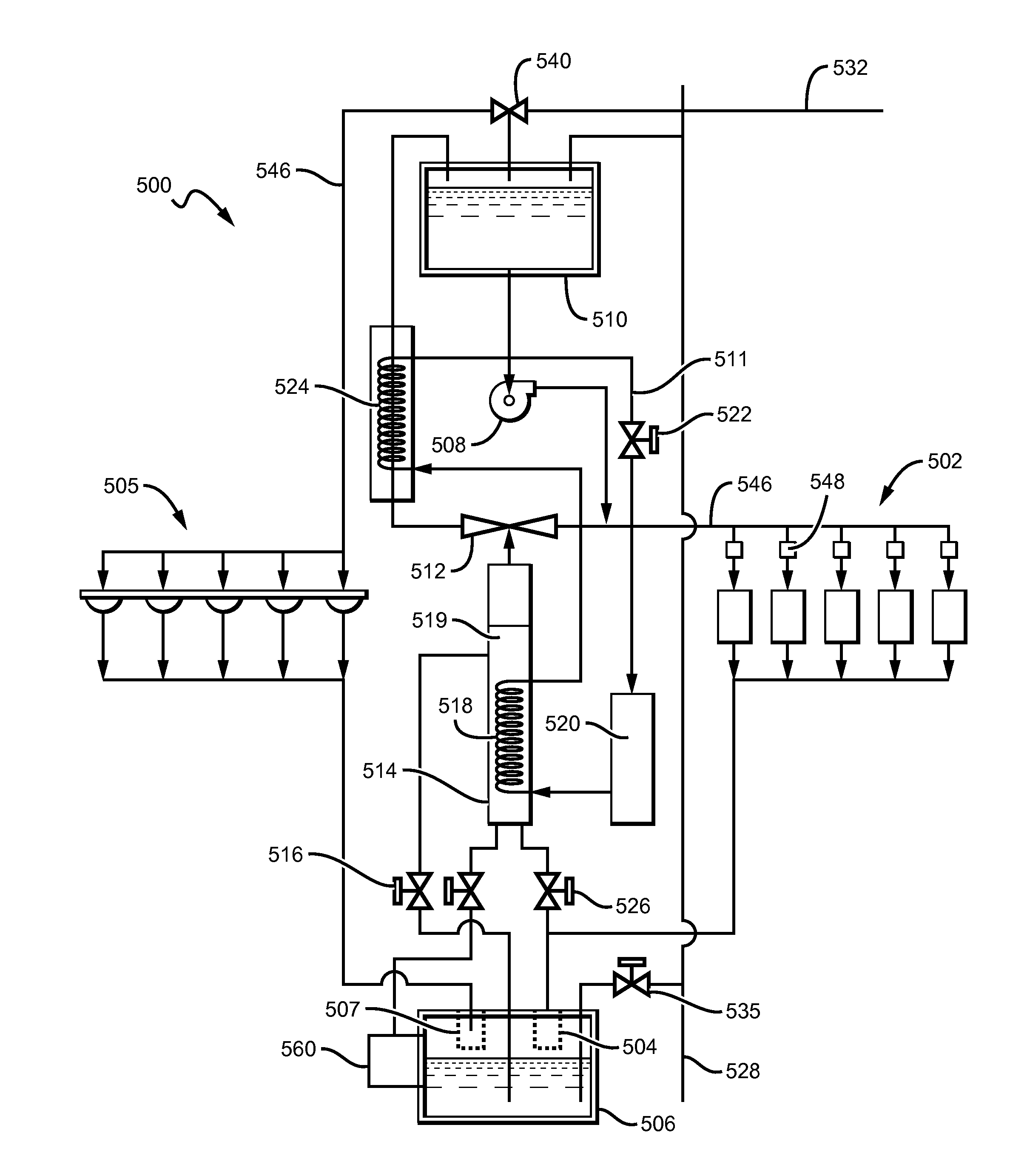
[0021]In an exemplary embodiment of a water recovery system 100 for processing wastewater into a flushing fluid shown in FIG. 1, wastewater can be piped from five urinals 102 through an optional filter 104 and into a holding tank 106. Filter 104 can be a strainer basket, a nano-electronic filter or other commercially suitable filter that advantageously removes debris and other solid contaminants from the wastewater. The wastewater can remain in the holding tank 106 until it is needed for processing. If the wastewater level in the holding tank 106 reaches a predetermined maximum level, the excess wastewater can flow from the holding tank 106 to a drain pipe 128. This can occur passively, similar to overflow holes found in sinks, or could occur actively, such as by the use of a level switch that signals a valve actuator to open a valve and allow the excess wastewater to flow to the drain pipe 128. Preferably, the drain pipe 128 includes a check-valve 134 or other one-way valve, such t...


PUM

PropertyMeasurementUnit
temperatureaaaaaaaaaa
pressuresaaaaaaaaaa
temperatureaaaaaaaaaa

Abstract

Systems and methods for processing wastewater into a flushing fluid are described, in which wastewater flows into a holding tank from one or more restroom fixtures. A vacuum distillator can be coupled to the holding tank, and a heater can be configured to heat at least a portion of the wastewater in the vacuum distillator to produce a vapor. The vapor can be condensed by a condenser fluidly coupled to the vacuum distillator to produce a distilled stream. The stream can either be fed into a tank or passed to one or more restroom fixtures.

Description

[0001]This application claims priority to U.S. provisional application having Ser. No. 61 / 379980 filed on Sep. 3, 2010. This and all other extrinsic materials discussed herein are incorporated by reference in their entirety. Where a definition or use of a term in an incorporated reference is inconsistent or contrary to the definition of that term provided herein, the definition of that term provided herein applies and the definition of that term in the reference does not apply.FIELD OF THE INVENTION[0002]The field of the invention is wastewater processing systems.BACKGROUND[0003]Traditional urinals, toilets, and other urine receptacles utilize potable water to flush restroom fixtures, which amounts annually to significant quantities of water that could otherwise be consumed for drinking or other uses. This constant need for potable water can be problematic, especially in areas with limited or no access to water. To reduce the water usage of restroom fixtures, low-flush and waterless...

Claims


Application Information

Patent Timeline
Patent Type & Authority Applications(United States)
IPC IPC(8): C02F1/04B01D3/10
CPCB01D3/007B01D3/10C02F1/001C02F1/048C02F2209/42C02F2103/002C02F2103/005C02F2303/04C02F2303/10C02F1/32Y02W10/30
Inventor FIMA, GIOVANNILANDON, FRANK
Owner LIQUIDBREAKER
Why Eureka
Try Eureka