RFID Label With Shielding Element

a shielding element and label technology, applied in the field of rfid structures, can solve the problems that rfid tags do not achieve optimal performance when placed on metallic objects, and achieve the effect of optimizing the on-metal performance of rfid labels/inlays and advantageously imporved performan

Inactive Publication Date: 2012-03-08
TAGSTAR SYST
View PDF2 Cites 42 Cited by
  • Summary
  • Abstract
  • Description
  • Claims
  • Application Information

AI Technical Summary

Benefits of technology

[0010]Any of the implementations can realize one or more of the following advantages. By optimizing a RFID inlay/label (antenna and/or chip) to an exsting shielding material, the RFID performance is advantageously imporved. In addition, this approch can provide flexiblity to use any shielding material in the market to optimize the

Problems solved by technology

Accordingly, typical RFID tags do not achieve optimal performance when placed on metallic objects, because the high frequency alternat

Method used


Image

  • RFID Label With Shielding Element
  • RFID Label With Shielding Element
  • RFID Label With Shielding Element

Examples


Embodiment Construction

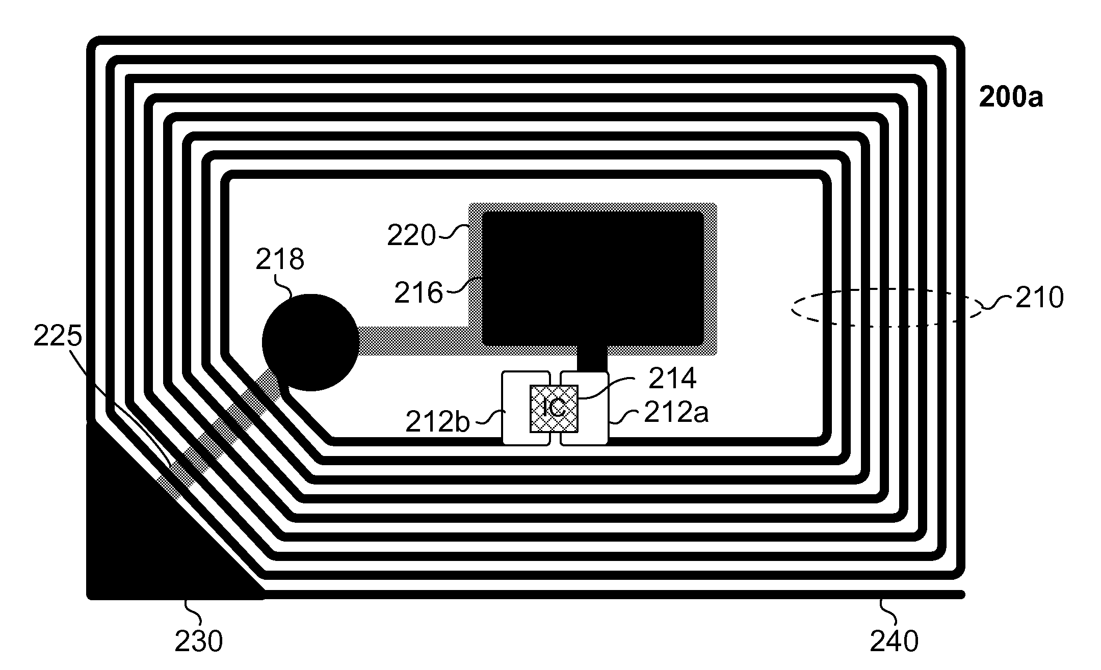
[0018]The present invention describes an improvement of the performance of RFID structures (e.g., RFID inlays, RFID labels) that use shielding material. In some embodiments in which the RFID structure is intended to be placed on a metallic object, optimization of RFID performance is achieved by tuning the RFID structure, including the antenna assembly and shielding layer, to closely align with a predetermined frequency range used by an RFID reader.

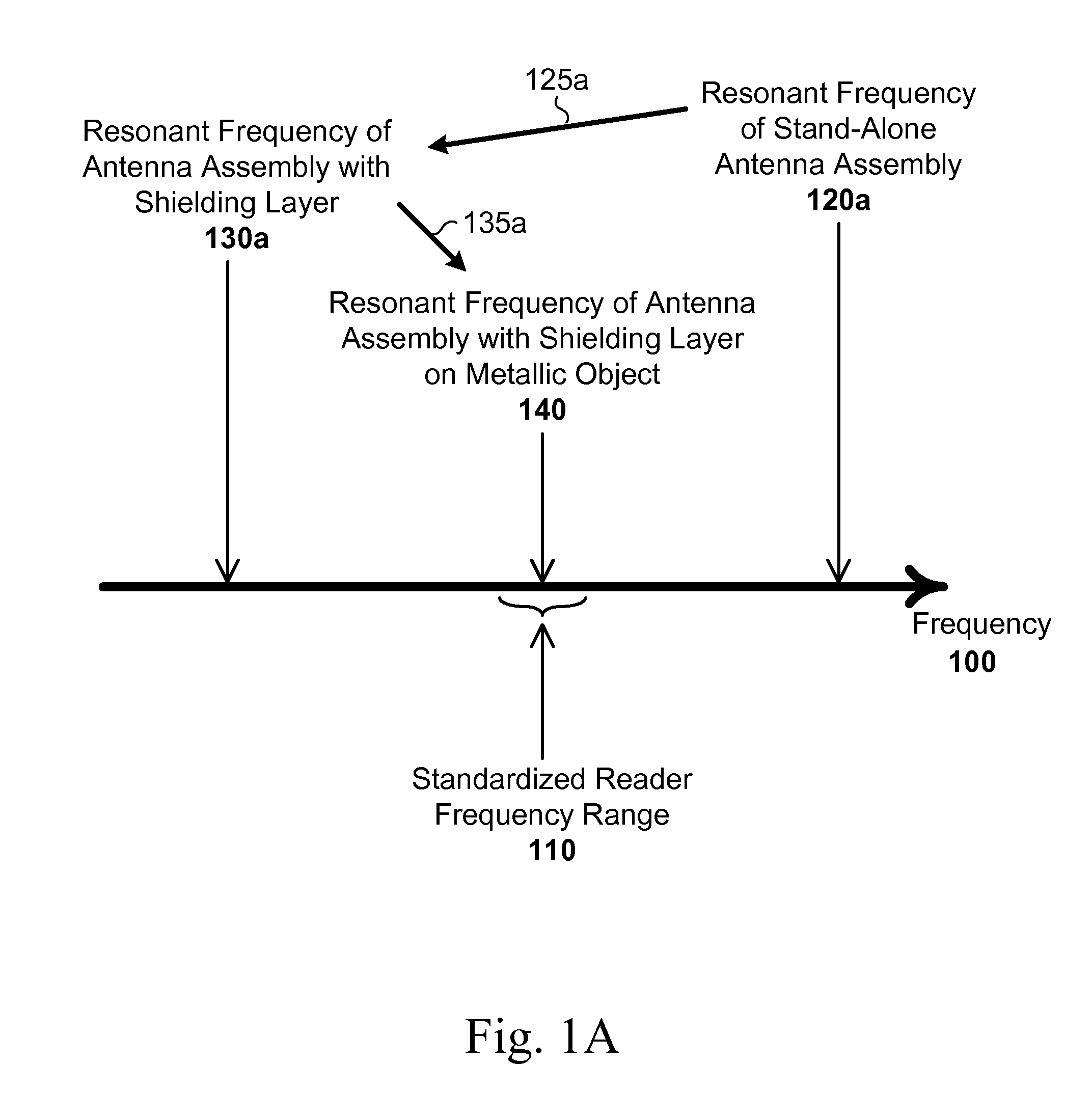
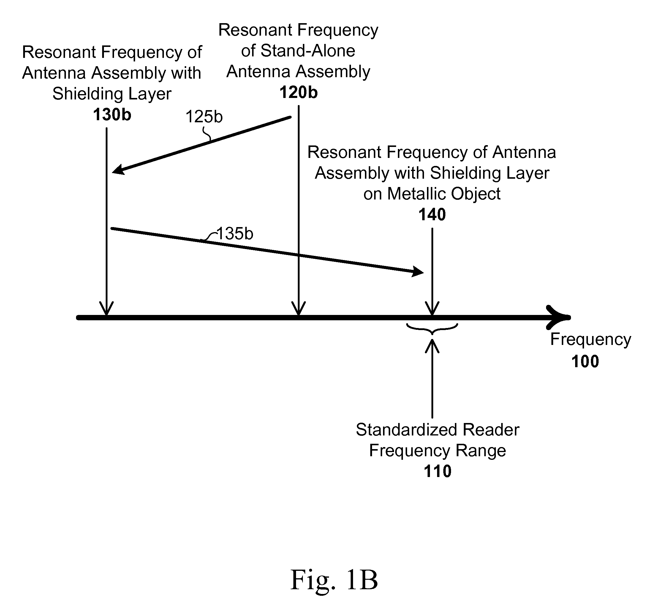
[0019]FIGS. 1A-1B are graphs illustrating resonant frequencies along a frequency axis 100. A RFID reader can generate alternating fields with a frequency within a predetermined frequency range 110. In some embodiments, the predetermined frequency range 110 conforms with one or more promulgated standards. For example, the International Telecommunication Union (ITU) Radiocommunication Sector (ITU-R) defines industrial, scientific and medical (ISM) radio bands for specific purposes. Examples of ISM bands used for RFID applications are: 6.765-...


PUM

PropertyMeasurementUnit
Frequencyaaaaaaaaaa
Frequencyaaaaaaaaaa
Frequencyaaaaaaaaaa

Abstract

Described are RFID structures and methods for forming RFID structures. An RFID structure includes a loop antenna assembly, an antenna substrate supporting the loop antenna assembly, and a shielding layer parallel with a plane defined by the antenna substrate. The loop antenna assembly has a stand-alone resonant frequency of ƒ1 above or below a standardized reader frequency range. The loop antenna includes an antenna track and at least two contact pads. The loop antenna assembly in combination with the shielding layer has a resonant frequency of ƒ2 below the standardized reader frequency range. If positioned against a metallic surface, the loop antenna assembly in combination with the shielding layer has a resonant frequency within the standardized reader frequency range.

Description

RELATED APPLICATIONS[0001]This application claims priority to and the benefit of U.S. Provisional Patent Application No. 61 / 380,627, filed on Sep. 7, 2010, the entire contents of which are incorporated herein by reference in their entirety.FIELD OF THE INVENTION[0002]The invention relates generally to RFID structures and methods for forming RFID structures.BACKGROUND OF THE INVENTION[0003]Radio-Frequency Identification (RFID) technology is directed to wireless communication between one object, typically referred to as a RFID tag, and another object, typically referred to as a RFID reader / writer. RFID readers / writers can generate high frequency magnetic fields, which can excite the transponder resonant circuit of the RFID tag via inductive energy transmission. RFID technology has been adopted, and is increasingly being used, in virtually every industry, including, for example, manufacturing, transportation, retail, and waste management. As such, reliable RFID systems are becoming inc...

Claims


Application Information

Patent Timeline
IPC IPC(8): G06K19/077H01P11/00
CPCG06K19/07749Y10T29/49016G06K19/07771H04B5/0081
Inventor MIESLINGER, STEFAN
Owner TAGSTAR SYST
Why Eureka
Try Eureka