Mobile solar energy system

a solar energy system and solar energy technology, applied in the direction of electrical apparatus construction details, electrical apparatus casings/cabinets/drawers, instruments, etc., can solve the problem of uninterrupted power supply, achieve the effect of reducing electromagnetic radiation, noise and pollutant emissions in operation, and improving mobility

Inactive Publication Date: 2012-03-08
LEE HSIANG YU +1
View PDF4 Cites 14 Cited by
  • Summary
  • Abstract
  • Description
  • Claims
  • Application Information

AI Technical Summary

Benefits of technology

[0010]A primary objective of the present invention is to receive a solar energy device in a chamber of a case and dispose a cover at a top opening of the chamber so that, when the sunlight propagates through the cover or impinges directly on solar panels, the solar energy can be transformed by a plurality of solar modules into the electric energy for charging a battery module. Thus, the solar energy device can be loaded inside the chamber of a standard case and then transported by a means of transportation conveniently with improved mobility. On the other hand, the solar energy device can significantly reduce the electromagnetic radiations, noises and pollutant emissions in operation as compared to the conventional outdoor power supplies (e.g., generators); also, this can avoid damage to the environment due to the need of laying cables from a long distance for connection with the utility power, and eliminate the need of additional labor hours and cost associated with laying of the cables.
[0011]A secondary objective of the present invention is to have the cover automatically opened or closed by means of a controlling device and have the solar panels driven by a lifting device to above the case and unfolded in a planar form or tilted at a predetermined angle. Thus, a large-area design can be adopted for the solar panels and the driving part can be designed in such a way that the solar panels rotate or move synchronously with the sun just like a sun tracking system. In this way, the light receiving area and the solar energy absorbed can be increased to provide a desirable electric power output efficiency; for example, the overall output power of the solar energy device may be as high as 5 kW or more.
[0012]A further objective of the present invention is to have the solar panels of the solar energy device aligned with the cover at the top opening of the chamber. The cover may be a fixed structure and formed of a transparent material. When the sunlight propagates through the cover to the solar panels, the excessive electric energy generated can be stored in the battery module so that power can be supplied uninterruptedly regardless of changes of the weather. Furthermore, when the case is moved to an outdoor environment where a power supply is unavailable (e.g., in case of a power failure, in a stricken area, at a large-scale concert or a mobile performance), the mobile solar energy system will not be affected by the rain, moisture, dust and the like; and this can also provide a desirable anti-theft function and makes the mobile solar energy system endurable.

Problems solved by technology

When the sunlight propagates through the cover to the solar panels, the excessive electric energy generated can be stored in the battery module so that power can be supplied uninterruptedly regardless of changes of the weather.

Method used


Image

  • Mobile solar energy system
  • Mobile solar energy system
  • Mobile solar energy system

Examples


Embodiment Construction

[0023]For better understanding of the aforesaid objectives and structures as well as the technical means and efficacies of the present invention, preferred embodiments of the present invention will be detailed with reference to the attached drawings.

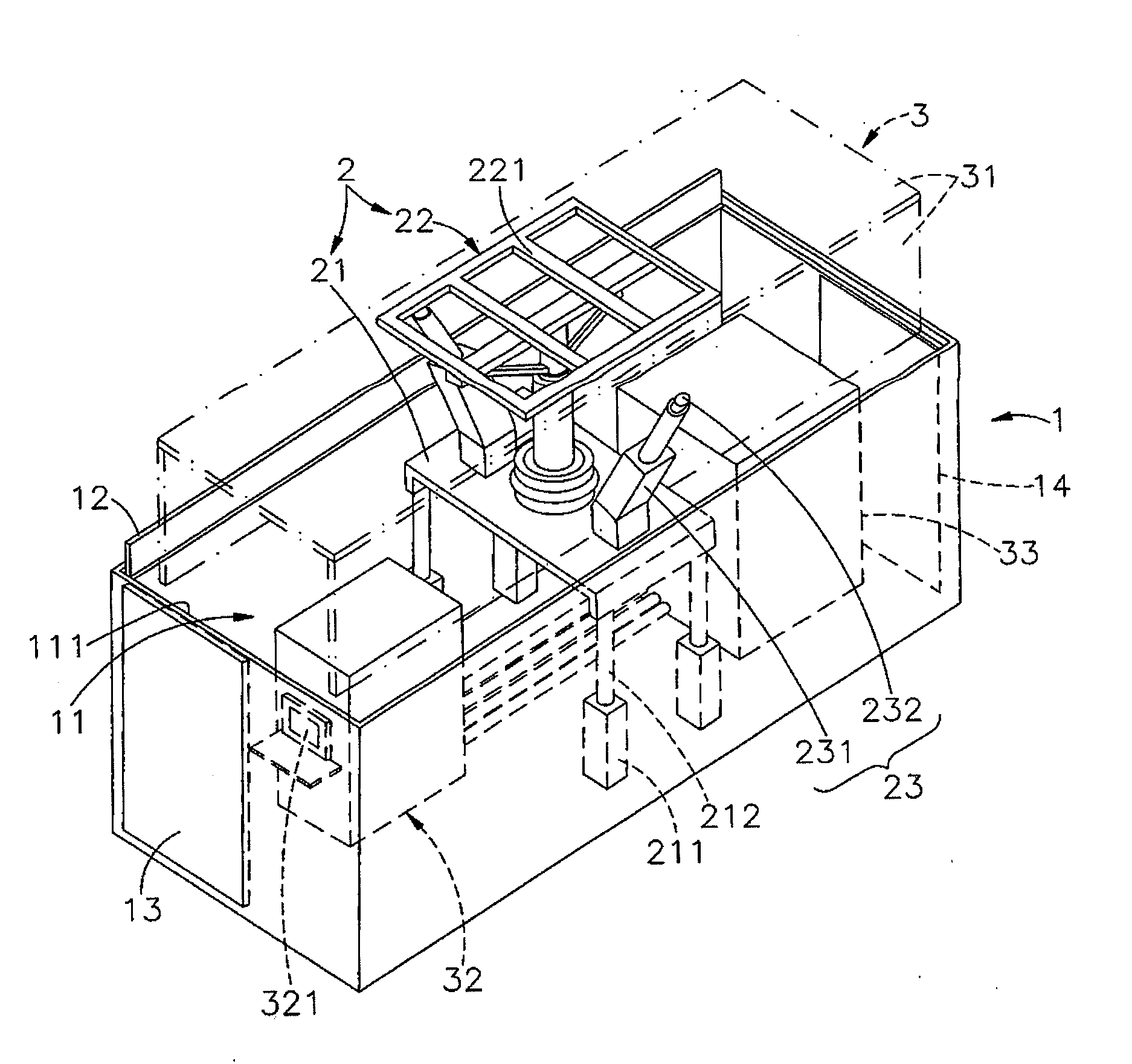
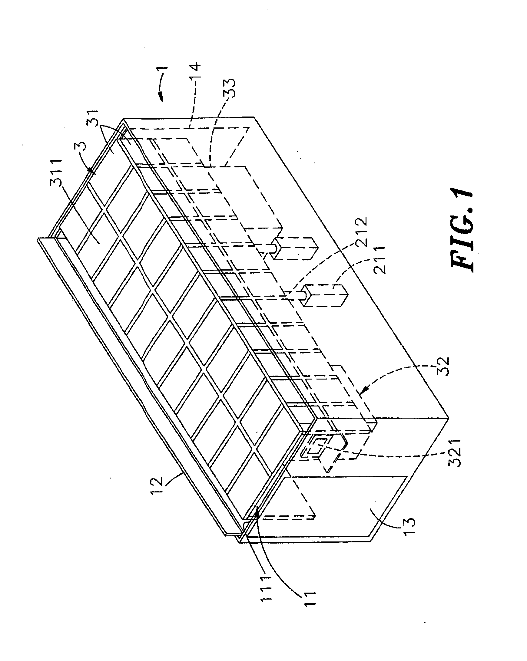
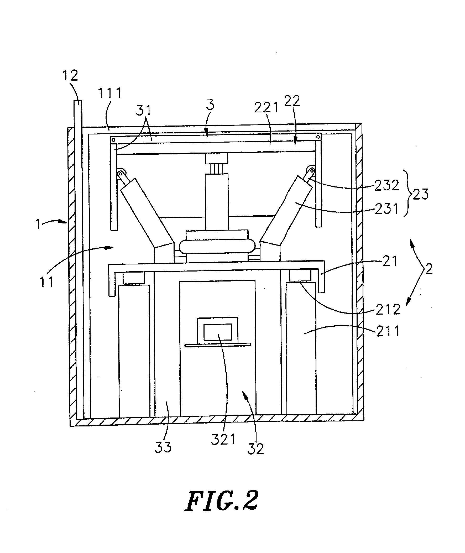
[0024]Referring to FIGS. 1, 2, 3, and 4 together, a perspective outside view of the present invention, a cross-sectional side view of the present invention, a perspective outside view (I) of the present invention when being used and a perspective outside view (II) of the present invention when being used are shown therein respectively. As can be seen clearly from these figures, the present invention comprises a case 1, a lifting device 2 and a solar energy device 3.

[0025]The case 1 may be a container, a car, a ship's cabin or some other case of a rectangular form, a polygonal form or the like used for shipping by vehicles, ships or other means of transportation. A chamber 11 for receiving the lifting device 2 and the solar energy device ...


PUM


Abstract

A mobile solar energy system is disclosed, which comprises a case and a solar energy device received in a chamber of the case. A cover is disposed above the chamber. The solar energy device comprises solar panels and a controlling device, and a plurality of solar modules are disposed on the solar panels. A battery module electrically connected to the controlling device is connected to the solar panels so that, when the sunlight propagates through the cover to the solar panels, the solar energy can be transformed into electric energy for charging the battery module. Thus, the solar energy device can be put into a standard case and transported in the case by a means of transportation, which makes it convenient to move with improved mobility; and a pollution-free and noise-free power supply can be provided by the solar energy device, which makes it more competitive in the market.

Description

[0001]This application claims the priority benefit of Taiwan patent application number 100103836 file on Feb. 1, 2011.BACKGROUND OF THE INVENTION[0002]1. Field of the Invention[0003]The present invention relates to a mobile solar energy system, and more particularly, to a mobile solar energy system that has a solar energy device received inside a case so that, when the sunlight propagates through the cover disposed above the case onto solar panels, the solar energy can be transformed into electric energy for charging a battery module and that allows the case to be transported by a means of transportation conveniently with improved mobility.[0004]2. Description of the Related Art[0005]Nowadays, creating green dwelling environments has become an idea promoted by various countries. However, in the highly civilized world, people's activities (e.g., all means of transportation that are powered by fossil oil emit carbon dioxide (CO2)) have caused the content of carbon dioxide in the air t...

Claims


Application Information

Patent Timeline
Patent Type & Authority Applications(United States)
IPC IPC(8): H05K7/00
CPCH02J7/355H02J7/35
Inventor LEE, CHIA-YU
Owner LEE HSIANG YU
Why Eureka
Try Eureka