Generating Acoustic Quiet Zone by Noise Injection Techniques

Active Publication Date: 2012-03-08
SPATIAL DIGITAL SYST
View PDF14 Cites 36 Cited by
  • Summary
  • Abstract
  • Description
  • Claims
  • Application Information

AI Technical Summary

Benefits of technology

[0060]An optimization processor in the feedback loop converts measurements from individual probes into performance indexes; which are called cost functions and must be positively definite. The summation of all cost functions is referred to as the total cost of the current performance measure for the injection arrays. The to-be-updated weights in the next iteration for individual elements of the injection arrays are calculated based on the gradient of the performance measur

Problems solved by technology

Acoustic interference is a phenomenon that is so prevalent in our current society that it is notoriously difficult to avoid.
Whether it be road noise being transmitted through a car frame to the car cabin, or noise generated by construction equipment, undesired noises permeate many facets of everyday life.
By definition, acoustic interference, which are undesired acoustic signals (sound), originates from a source external to a desired signal path and produces undesired artifacts in the desired signal.
Acoustic interference may be the source of many problems associated with sound in our society today.
Excessive amounts of noise can pose a health risk for the majority of the population, as hearing loss is a major concern.
Excessive waste noise also causes problems, as it may devalue property (such as a house living near a railroad), make the area uncomfortable, among other things.
Additionally, some noises may just be uncomfortable or undesirable, such as the snores of a partner, or the road noise within a car.
When the phase-inverted noise is produced by the spe

Method used


Image

  • Generating Acoustic Quiet Zone by Noise Injection Techniques
  • Generating Acoustic Quiet Zone by Noise Injection Techniques
  • Generating Acoustic Quiet Zone by Noise Injection Techniques

Examples


Embodiment Construction

[0070]The proposed acoustic quiet zone generation technique features injection of the undesired acoustic noise at low power levels for cancellations. The noise mitigation technique comprises an auxiliary acoustic injection array with iterative processing to maintain a dynamic acoustic quiet zone over user-located areas.

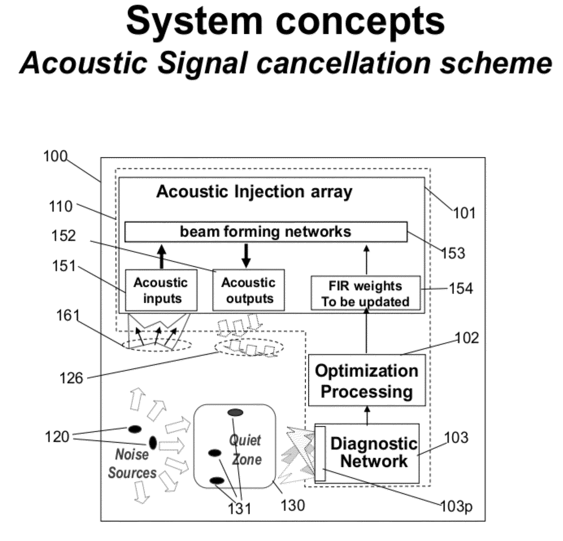
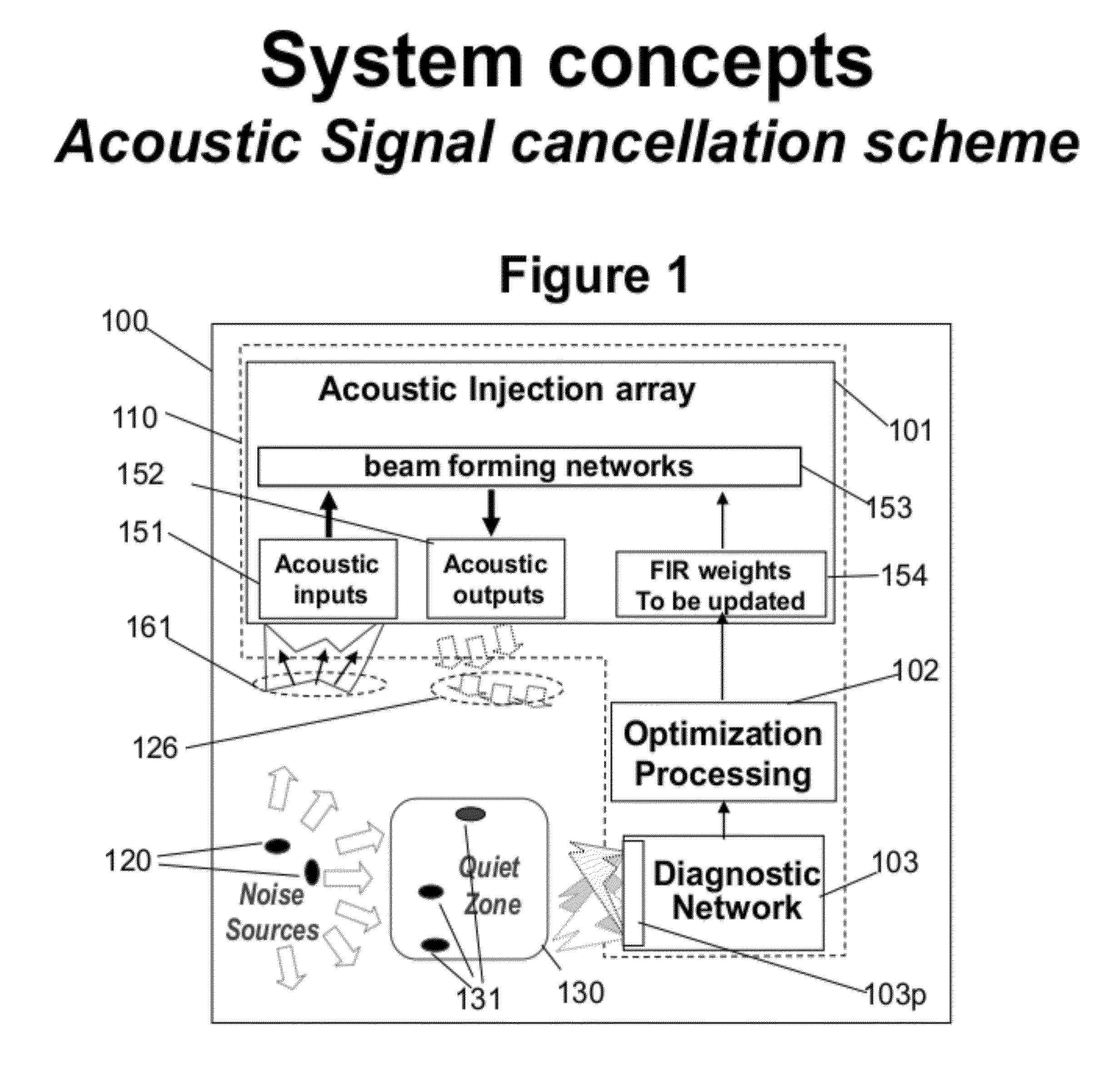
[0071]FIG. 1 depicts the functional blocks of the acoustic signal cancellation apparatus (100). One such a design (110) features the following functions: (1) an acoustic Injection array (101), (2) optimization processing (102), and (3) diagnostic network (103).

[0072]Acoustic injection array (101) consists of (1) an array of pickup sensors as M acoustic inputs (151) to pick up acoustic noise signals from noise sources (120) in real time, (2) a beam forming network (BFN) (153) with an M-to-N distribution network, and (3) an array of N acoustic signal injectors (152). The M-to-N BFN (112), where M=number of acoustic inputs (151) and N=acoustic outputs (152), feature elec...


PUM


Abstract

A quiet zone generation technique for acoustic/audio signals is proposed for mitigation of selected noise or interferences over limited areas in free space by injecting the very acoustic noise, interference, or audio feedback signals via iterative processing, generating quiet zones dynamically. This creates undesired noise-free quiet zones. Optimization loops operating iteratively to electronically process cancellation signals consist of three interconnected functional blocks: (1) an acoustic injection array, consisting of pick-up arrays to obtain the interference signals, beam forming networks for element weighting and/or re-positioning, and array elements for noise injections, (2) a diagnostic network with strategically located probes, and (3) an optimization processor with cost minimization algorithms to calculate element weights for updating.

Description

RELATED APPLICATION DATA[0001]This application is extension of U.S. patent application Ser. No. 12 / 874,437, filed Sep. 2, 2010.BACKGROUND OF THE INVENTION[0002]1. Field of the Invention[0003]The present invention relates to architectures and designs of mitigation techniques for undesired acoustic noises. In particular, the present invention pertains to acoustic devices generating acoustic signal quiet zones for undesired noise mitigation, while simultaneously retaining desired acoustic signals at acceptable levels.[0004]Several possible applications include, but are not limited to: 1) mitigation or elimination of road noise for in-car audio applications, 2) mitigation or elimination of engine noise for aeronautical applications, such as creation of individual quiet zones for passenger planes 3) mitigation of loud noises in enclosed areas such as cancellation of snoring in a bedroom, 4) creation mobile quiet zones, such as for music event type applications in relation to sound checki...

Claims


Application Information

Patent Timeline
IPC IPC(8): G10K11/16
CPCG10K11/178G10K2210/3215G10K2210/128G10K2210/12G10K11/17857G10K11/348G01S19/215G10K11/34G10K11/341
Inventor CHANG, DONALD C. D.CHEN, STEVE
Owner SPATIAL DIGITAL SYST
Why Eureka
Try Eureka