Photovoltaic modules

Inactive Publication Date: 2012-03-15
CERTAINTEED CORP
View PDF8 Cites 22 Cited by
  • Summary
  • Abstract
  • Description
  • Claims
  • Application Information

AI Technical Summary

Benefits of technology

[0012]According to another aspect, a roofing element includes a photovoltaic element, a substrate coupled to the photovoltaic element, wherein the substrate comprises an amorphous phase, wherein the substrate has a surface region under a compressive stress of at least about 200 MPa. The roo

Problems solved by technology

Alternative energy sources continue to be in greater demand to stem our reliance upon fossil fuels, since fossil fuels are proven to be in limited supply and difficult to find, store, and distribute.
Additionally, fossil fuels are becoming more expensive due

Method used


Image

  • Photovoltaic modules
  • Photovoltaic modules
  • Photovoltaic modules

Examples


Example

[0025]The use of the same reference symbols in different drawings indicates similar or identical items.

DETAILED DESCRIPTION

[0026]The following is directed to photovoltaic modules. As used herein, the term “photovoltaic module” means one or more photovoltaic cells electrically connected to operate as an integral unit. “Infrared radiation” means electromagnetic radiation having a wavelength of from 1.4 micrometers to 1000 micrometers. “Near infrared radiation” means electromagnetic radiation having a wavelength of from 0.75 micrometers to 1.4 micrometers. “Visible radiation” means electromagnetic radiation having a wavelength of from 350 to 750 nanometers. “Substantially transmissive” when referring to radiation means having an average transmission coefficient of at least 50 percent.

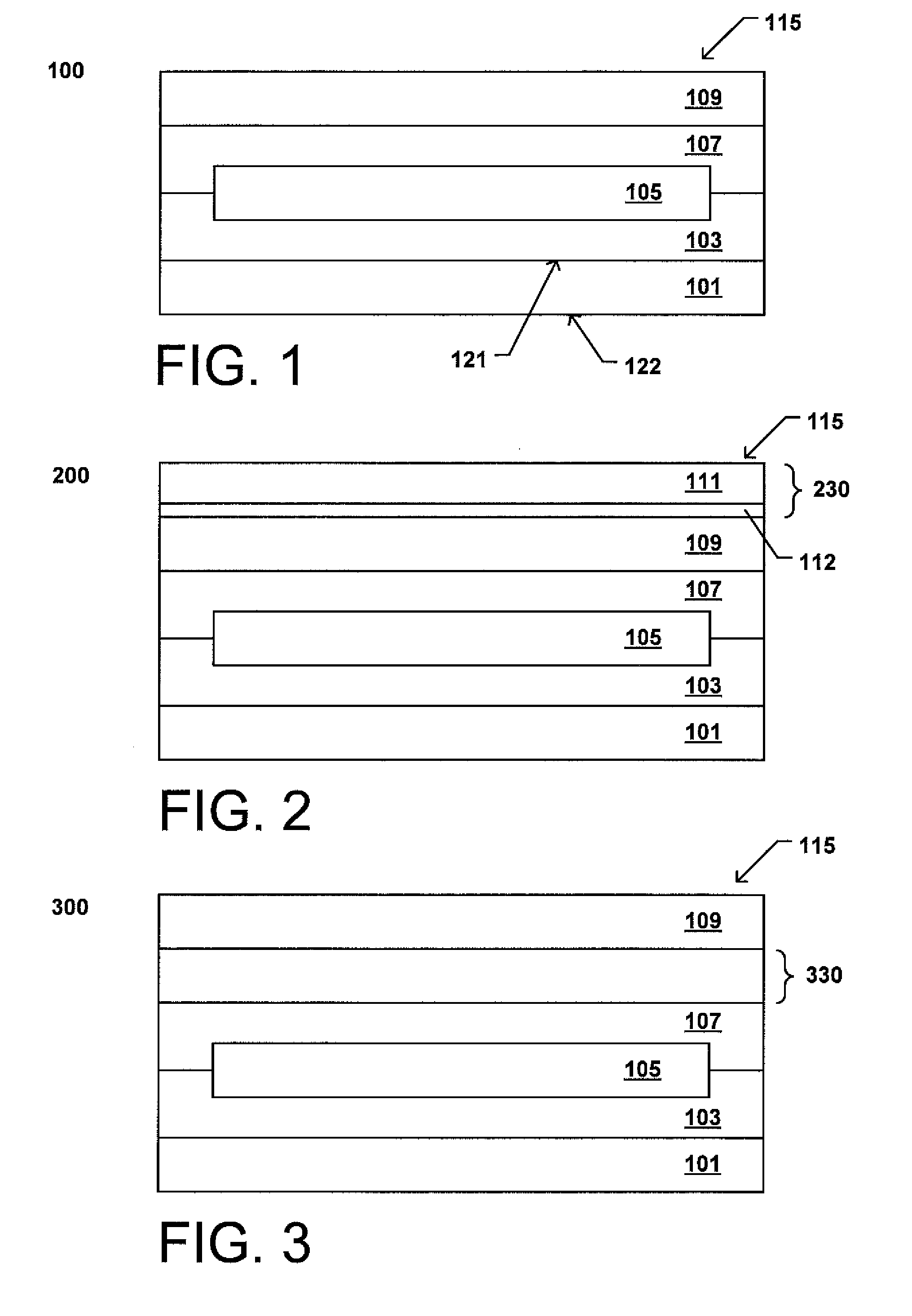
[0027]FIG. 1 includes a cross-sectional diagram of a photovoltaic module according to an embodiment. As illustrated, the photovoltaic module 100 can include a photovoltaic element 105, which can include on...


PUM


Abstract

A photovoltaic module includes a photovoltaic element, and a substrate coupled to the photovoltaic element comprising an amorphous phase material, wherein the substrate comprises a compression region abutting an external surface of the substrate. Additionally, the compression region extends for an average depth into the substrate of at least about 50 microns.

Description

CROSS-REFERENCE TO RELATED APPLICATION(S)[0001]The present application claims priority from U.S. Provisional Patent Application No. 61 / 382,443, filed Sep. 13, 2010, entitled “PHOTOVOLTAIC MODULES,” naming inventor Gregory F. Jacobs, which application is incorporated by reference herein in its entirety.BACKGROUND[0002]1. Field of the Disclosure[0003]The following is directed to photovoltaic modules, and more particularly substrates for use with certain photovoltaic modules.[0004]2. Description of the Related Art[0005]Alternative energy sources continue to be in greater demand to stem our reliance upon fossil fuels, since fossil fuels are proven to be in limited supply and difficult to find, store, and distribute. Additionally, fossil fuels are becoming more expensive due to increasing scarcity and political issues surrounding the limited supply. It is also worth noting that fossils fuels have been shown to have negative effects on the global environment, including for example, air po...

Claims


Application Information

Patent Timeline
IPC IPC(8): E04D13/18H01L31/048
CPCH01L31/02366H01L31/0392H02S20/25Y02B10/12Y02E10/50H01L31/0481H01L31/03923H01L31/03925Y02B10/10Y02E10/541
Inventor JACOBS, GREGORY F.
Owner CERTAINTEED CORP
Why Eureka
Try Eureka