Exhaust gas control apparatus for engine

a technology of exhaust gas control apparatus and internal combustion engine, which is applied in the direction of engine controllers, combustion engines, machines/engines, etc., can solve the problems of increasing the cost, affecting the reliability of the turbocharger, and the structure of the exhaust pipe of the engine may become complicated, so as to prevent the malfunction of the independent two valves and the deterioration of accuracy , the effect of avoiding the generation of clearan

Inactive Publication Date: 2012-03-15
DENSO CORP
View PDF12 Cites 66 Cited by
  • Summary
  • Abstract
  • Description
  • Claims
  • Application Information

AI Technical Summary

Benefits of technology

[0033]The present invention is made in view of the above problems. It is an object of the present invention to provide an exhaust gas control apparatus for an internal combustion engine, which can be easily mounted on the engine, which is lower in weight, and which is lower in cost. It is also an object of the present invention to provide an exhaust gas control apparatus for the engine, according to which an operational force for an actuator may be decreased.
[0034]It is another object of the present invention to provide a turbocharger, according to which two independent valves (for example, a variable capacitor type valve and a waste-gate valve) are operated by one actuator, and according to which a deformation of a cam plate by heat is prevented and possible generation of a clearance between the cam plate and a link is prevented.

Problems solved by technology

In other words, since it becomes necessary to provide two actuators, a structure of an exhaust pipe of the engine may become complicated and a cost is increased.
In the same manner to the first prior art, it is necessary to provide two actuators, and thereby a structure of an exhaust pipe of the engine may become complicated and a cost is increased.
As a result, the opening degree of the variable nozzle or the waste-gate valve may not be stably controlled, and thereby control accuracy for the flow rate may be decreased and furthermore slapping sound may be generated when the link mechanism is changed from the idling stroke to a working stroke.
It is, therefore, a problem that an operational force of the electric actuator 108 is increased.
It is, therefore, a factor for increasing cost, size and weight of the turbocharger.
Therefore, there is a demand that both of the variable capacitor type valve and the waste-gate valve are operated by one actuator (for example, an electric actuator being composed of an electric motor and a reduction gear) in order to achieve a miniaturization, a decrease of weight, a cost-down of the apparatus.

Method used


Image

  • Exhaust gas control apparatus for engine
  • Exhaust gas control apparatus for engine
  • Exhaust gas control apparatus for engine

Examples


first embodiment

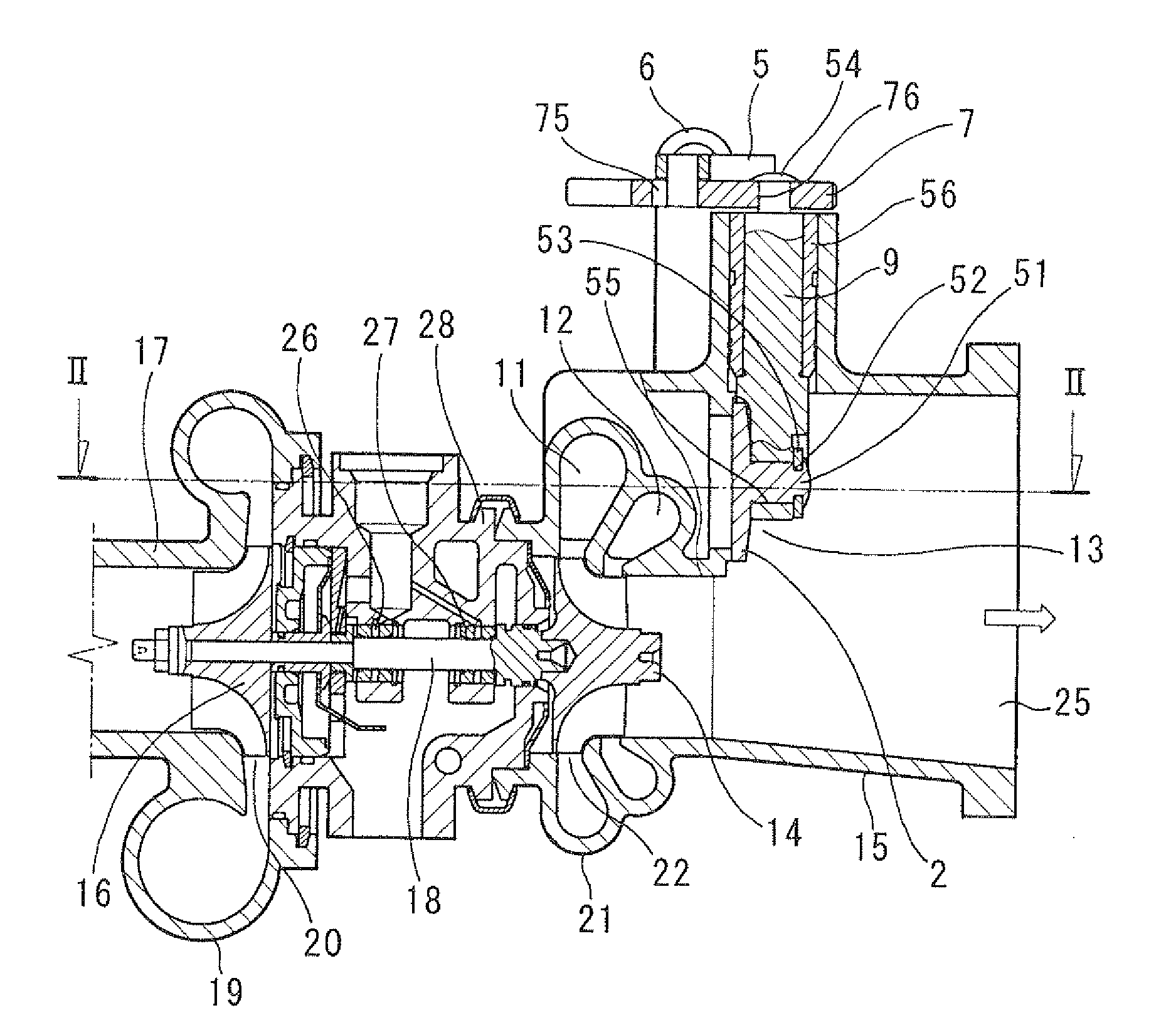
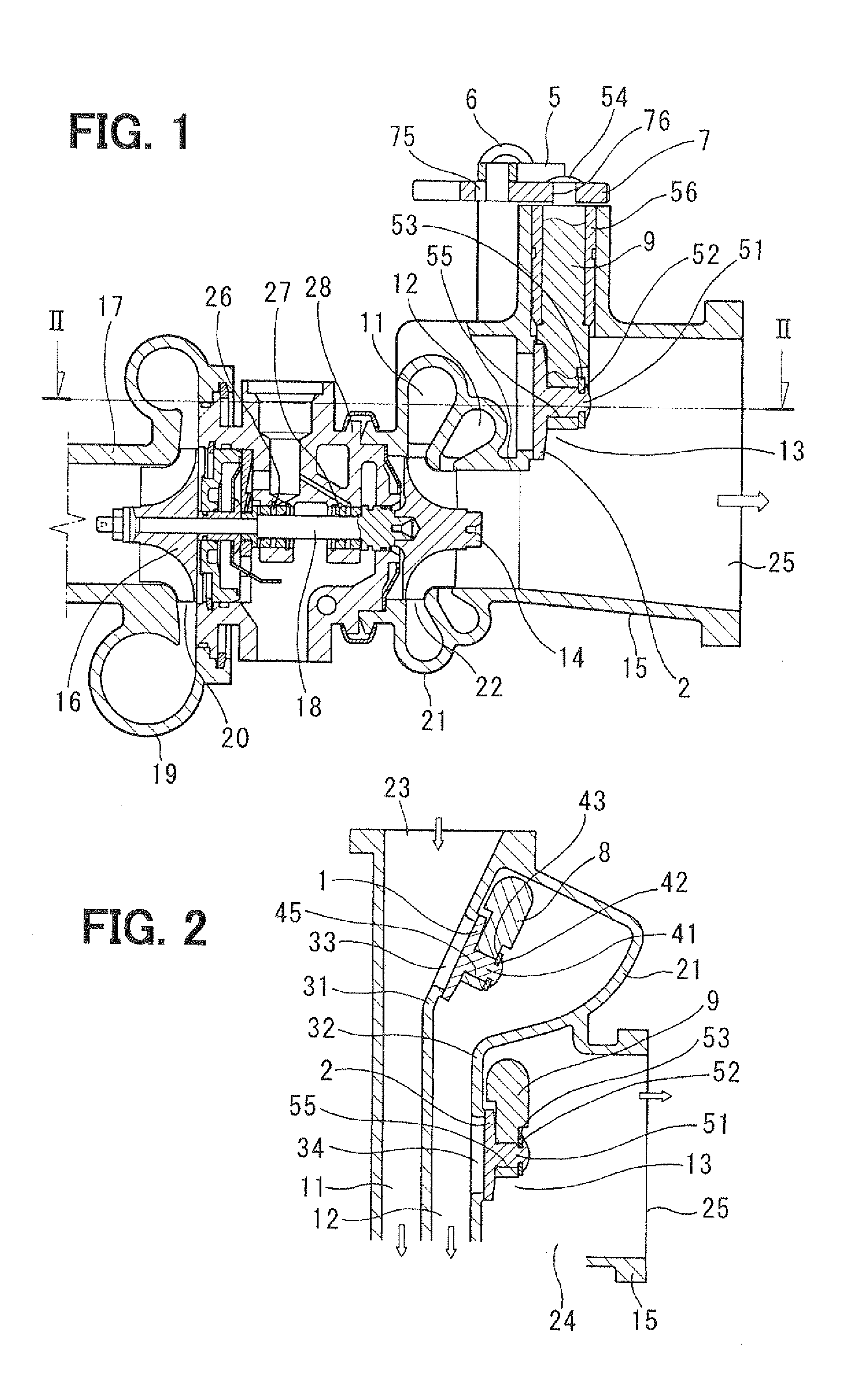
[0070]FIGS. 1 to 6 show a first embodiment of the present invention, wherein FIGS. 1 and 2 show a supercharging pressure control apparatus for an internal combustion engine.

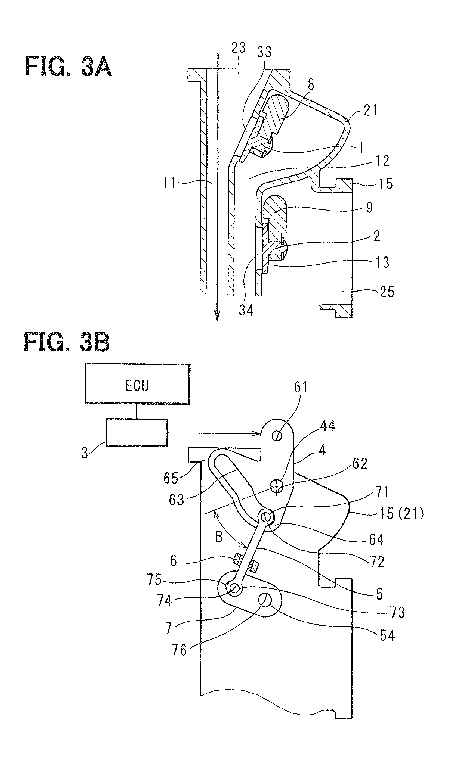
[0071]A control apparatus for the engine (an engine control system) according to the present embodiment is composed of a supercharging pressure control apparatus for controlling supercharging pressure of the engine and an electronic engine control unit (ECU) for controlling an operation of the supercharging pressure control apparatus. The control apparatus of the present embodiment is used as an exhaust gas control apparatus for the engine for controlling exhaust gas discharged from combustion chambers of respective cylinders.

[0072]As shown in FIGS. 1 to 5 (5A and 5B), the supercharging pressure control apparatus is composed of a turbocharger for supercharging intake air into combustion chambers of the respective cylinders of the engine and a valve driving device. The valve driving device has a flow rate control ...

second embodiment

[0200]A second embodiment of the present invention will be explained with reference to FIGS. 7 to 12. The same reference numerals to the first embodiment are used in the second embodiment for designating the same or similar parts or portions.

[0201]As already explained in the first embodiment, the turbocharger for the engine is composed of (as shown in FIGS. 7 and 8);[0202]the turbine wheel 14 rotated by the exhaust gas from the engine;[0203]the turbine housing 15 formed in a spiral shape for accommodating the turbine wheel 14;[0204]the compressor wheel 16 driven by the rotational force of the turbine wheel 14 so as to compress the intake air;[0205]the compressor housing 17 of a spiral shape for accommodating the compressor wheel 16;[0206]the turbine shaft 18 for transmitting the rotational force of the turbine wheel 14 to the compressor wheel 16; and[0207]the bearing housing (also referred to as the center housing) 28 for rotatably supporting the turbine shaft 18.

[0208]The center ho...


PUM


Abstract

A flow rate control valve and a waste-gate valve are operatively linked to a common cam plate, which is driven by an actuator. The cam plate has a first driving portion for rotating the flow rate control valve in a synchronized manner with rotation of the cam plate. The cam plate has a second driving portion for rotating the waste-gate valve in accordance with the rotation of the cam plate, wherein an operational pattern for the waste-gate valve is different from that for the flow rate control valve. As above, two valves are operated by one actuator so as to move independently from each other.

Description

CROSS REFERENCE TO RELATED APPLICATION[0001]This application is based on Japanese Patent Applications No. 2010-201779 filed on Sep. 9, 2010 and No. 2010-206861 filed on Sep. 15, 2010, the disclosures of which are incorporated herein by reference.FIELD OF THE INVENTION[0002]The present invention relates to an exhaust gas control apparatus for an internal combustion engine, in particular, relates to a supercharging pressure control apparatus for controlling supercharging pressure of an internal combustion engine having a turbocharger.[0003]The present invention further relates to a turbocharger having two independent valves, in particular, relates to a driving device for such two valves.BACKGROUND OF THE INVENTION[0004]A supercharging pressure control apparatus is known in the art, for example, as disclosed in Japanese Utility Model Publication No. S62-162349 (also referred to as Prior Art Publication 1), according to which supercharging pressure is controlled for an internal combusti...

Claims


Application Information

Patent Timeline
Patent Type & Authority Applications(United States)
IPC IPC(8): F02B37/16F02B37/00
CPCF02B37/025Y02T10/144F02B37/186F02B37/183Y02T10/12
Inventor SATO, OSAMUYANAGIDA, ETSUGOU
Owner DENSO CORP
Why Eureka
Try Eureka