Method of manufacturing optical component and apparatus for manufacturing optical component

a manufacturing method and technology for optical components, applied in the field of manufacturing optical components, can solve the problems of reducing long molding time, and long time, and achieve the effect of improving the optical performance of molded products and reducing molding tim

Active Publication Date: 2012-03-15
CANON KK
View PDF4 Cites 3 Cited by
  • Summary
  • Abstract
  • Description
  • Claims
  • Application Information

AI Technical Summary

Benefits of technology

[0015]One aspect of the present invention provides a method of manufacturing an optical component and an apparatus for manufacturing such an optical component. In the method and apparatus, an infrared transmitting mold and an infrared irradiator are used as heating units and the molding time is reduced and the optical performance of a molded product is improved by intensively heating a surface of a substrate.
[0018]According to at least one embodiment of the present invention, the time taken for heating and cooling can be reduced by intensively heating a surface of a substrate. That is, the molding time can be reduced. Since an inner portion of the substrate can be prevented from being heated, the density distribution and birefringence of the substrate can be prevented from varying during molding. Furthermore, when the substrate is a near shaped gob that has been reduced in density distribution and birefringence by annealing, an optical component having a small density distribution, low birefringence, and high optical performance can be prepared from the substrate.

Problems solved by technology

When the molded product is an optical component for transmitting light like a lens, there is a problem in that the molded product has reduced optical performance due to the internal density distribution and birefringence of the molded product that are caused by shrinkage.
Furthermore, there is a problem in that the molding time is long because the resin material is entirely melted and cooling takes a long time.
Therefore, there is a problem in that the molding time is long because press molding takes a longer time for heating and cooling than injection molding.
However, the stamp transmits infrared light and therefore the temperature thereof hardly increases.
Conventional techniques have the effect of increasing the transferability of substrates by heating surfaces of the substrates and are, however, incapable of intensively heating the substrate surfaces.
Therefore, density distribution and birefringence are caused in molded products during cooling and solidification, leading to a problem with a reduction in optical performance.
Furthermore, the use of ultraviolet light as a light source deteriorates resin to cause a reduction in optical performance.

Method used


Image

  • Method of manufacturing optical component and apparatus for manufacturing optical component
  • Method of manufacturing optical component and apparatus for manufacturing optical component
  • Method of manufacturing optical component and apparatus for manufacturing optical component

Examples


first embodiment

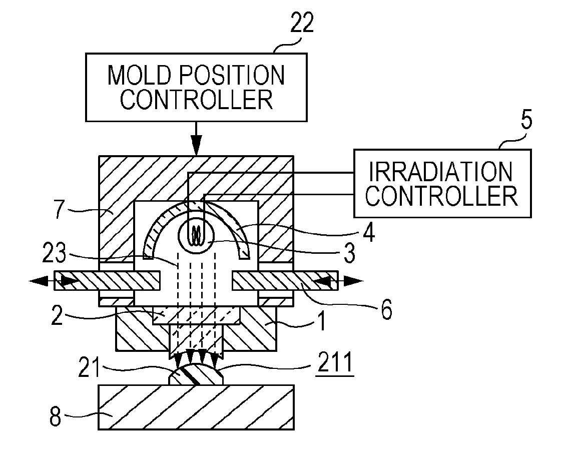
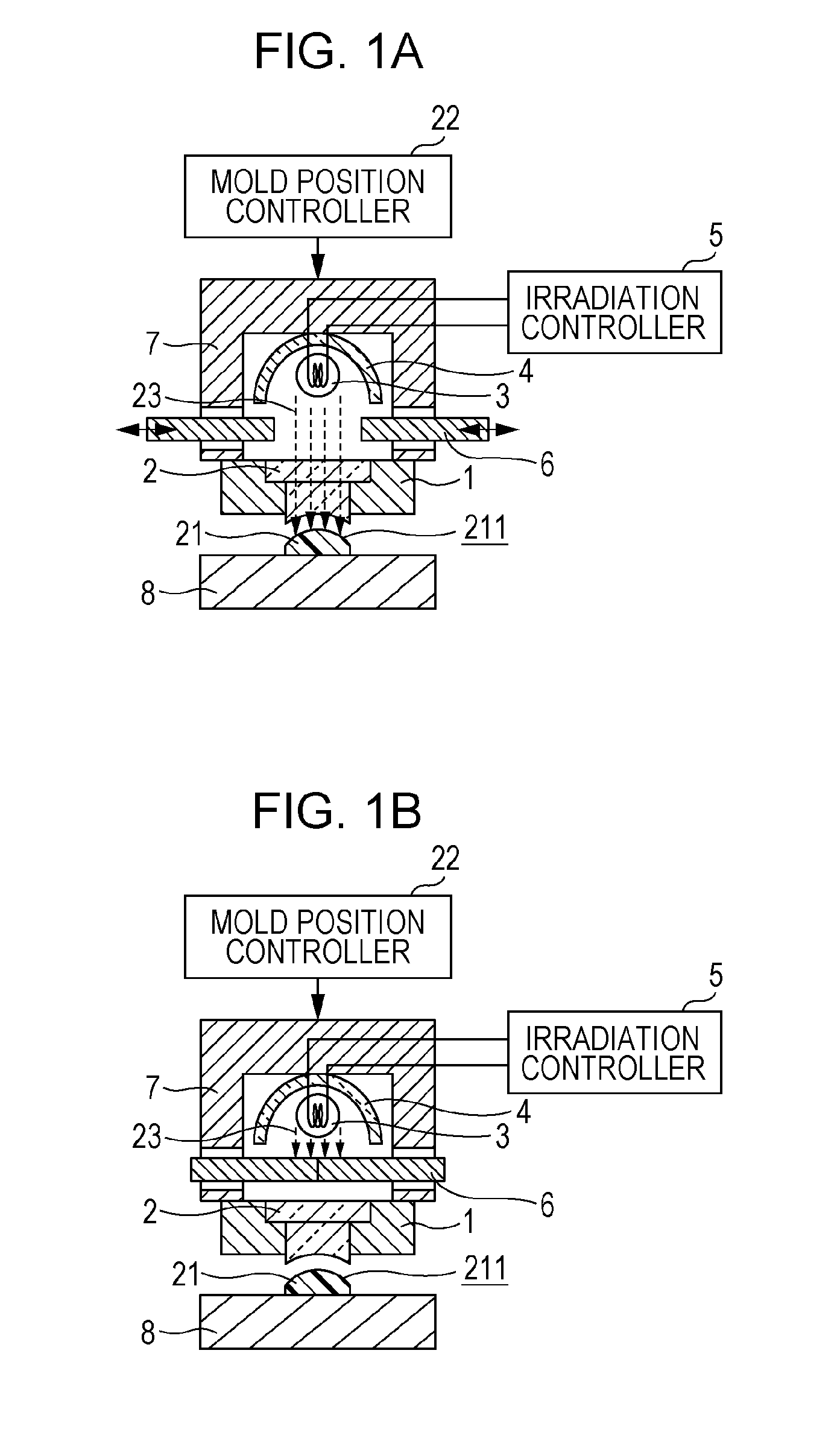
[0034]FIG. 1 is a schematic view of a press molding machine corresponding to an apparatus for manufacturing an optical component according to a first embodiment the present invention. With reference to FIG. 1, reference numeral 2 represents a mold including at least one portion made of an infrared transmitting material (for example, quartz glass). The mold 2 is retained with a mold support 1 and is attached to a press unit 7. The press unit 7 includes an infrared irradiator 3 including a carbon lamp. An infrared ray 23 (may also be referred to as infrared beam or infrared light) emitted from the infrared irradiator 3 is directed to the mold 2 by a condenser mirror 4 and is thereby applied to a substrate 21 made of resin.

[0035]The intensity of the infrared ray 23 is controlled with an irradiation controller 5 and the irradiation of the substrate 21 with the infrared ray 23 is controlled by the switching operation of a shutter 6 in an on / off manner.

[0036]In this embodiment, the press ...

second embodiment

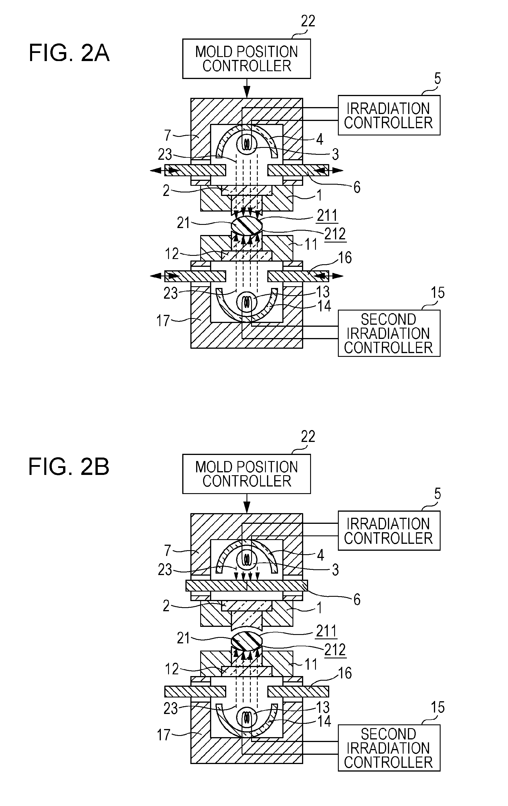
[0054]An apparatus for manufacturing an optical component according to a second embodiment of the present invention will now be described with reference to FIGS. 2A and 2B. FIGS. 2A and 2B illustrate a schematic view of a press molding machine corresponding to the apparatus according to the second embodiment. In FIGS. 2A and 2B, the same portions as those shown in FIGS. 1A and 1B are denoted by the same reference numerals. Thus, reference numerals already described as those used in FIG. 1 will not be described in detail. In this embodiment, the surface 211 of the substrate 21 described in the first embodiment is shaped and a second surface 212 of the substrate 21 that is opposite to the first surface 211 thereof is also shaped with a second mold 12.

[0055]With reference to FIG. 2A, the second mold 12 is placed on the opposite side of the substrate 21 from the mold 2. The second surface 212 of the substrate 21 is shaped with the second mold 12. The second mold 12 includes at least one...

third embodiment

[0072]An apparatus for manufacturing an optical component according to a third embodiment of the present invention will now be described. FIG. 3 is a schematic view of a press molding machine corresponding to the apparatus according to the third embodiment. The same portions as those shown in FIG. 2 are denoted by the same reference numerals as those used in FIG. 2 and will not be described in detail. In this embodiment, an automatic hand 24 (e.g., robotic positioned) holds and positions a substrate 21. Other components are substantially the same as those described in the second embodiment. A method of manufacturing an optical component according to this embodiment is described below.

[0073]Before manufacturing steps are started, a shutter 6 and a second shutter 16 are closed and an infrared irradiator 3 and a second infrared irradiator 13 are turned on in advance.

[0074]The automatic hand 24 is suspended in such a state that the substrate 21 is held by the automatic hand 24 and the g...


PUM

PropertyMeasurementUnit
temperatureaaaaaaaaaa
peak wavelengthaaaaaaaaaa
speedaaaaaaaaaa

Abstract

A method of manufacturing an optical component includes, bringing a mold including at least one portion made of an infrared transmitting material into tight contact with a substrate, heating the substrate by irradiating the substrate with an infrared ray in a state that a gap is present between the substrate and the mold, and placing the mold and the substrate into tight contact with each other.

Description

BACKGROUND OF THE INVENTION[0001]1. Field of the Invention[0002]The present invention relates to a method of manufacturing an optical component such as a lens and an apparatus for manufacturing the optical component.[0003]2. Description of the Related Art[0004]Optical components made of resin are usually manufactured by injection molding, press molding, or a similar method.[0005]In injection molding, a molten plasticized resin material is filled in a cavity of a mold and is then cooled, whereby a molded product with a desired shape is obtained. Since the resin material is cooled by the transfer of heat from the resin material to the mold, a surface portion of the resin material that is in contact with the mold solidifies initially and an inner portion thereof then solidifies gradually. In this course, cooling shrinkage occurs; hence, a surface portion of the molded product that has solidified initially is high in density and an inner portion thereof is low in density.[0006]When the ...

Claims


Application Information

Patent Timeline
Patent Type & Authority Applications(United States)
IPC IPC(8): B29D11/00B29C35/08
CPCB29B13/023B29D11/00432B29C2035/0822B29C35/0805
Inventor TAKATA, ATSUSHIOGANE, MASANOBU
Owner CANON KK
Why Eureka
Try Eureka