
Wind turbine generator and tidal current generator

Active Publication Date: 2012-03-15
MITSUBISHI HEAVY IND LTD
View PDF8 Cites 21 Cited by
  • Summary
  • Abstract
  • Description
  • Claims
  • Application Information

AI Technical Summary

Benefits of technology

[0048]According to the present invention, the wind turbine generator or the tidal current generator uses the hydraulic transmission including the combination of the hydraulic pump and the hydraulic motor and thus, it is possible to reduce the weight and cost of the wind turbine generator in comparison with a conventional wind turbine generator or the tidal current generator using a mechanical gearbox.
[0049]Further, to adopt the hydraulic transmission comprising various parts such as the cylinder, the piston, the cam, the high pressure valve and the low pressure valve, the hydraulic transmission is at least partially formed by a plurality of modules, and thus the productivity and the maintainability is improved. Specifically, by forming the hydraulic transmission by the module, the hydraulic transmission can be easily assembled and the productivity of the wind turbine generator and the tidal current generator is improved. Further, even when the hydraulic transmission breaks down, the modules can be individually replaced, that is only the module causing the failure needs to be replaced. As a result, the maintenance can be easily performed on the wind turbine generator and the tidal current generator.
[0050]Furthermore, by changing the number of the modules of the hydraulic transmission depending on the desired output, a variety of turbine generators with different output can be efficiently produced.

Problems solved by technology

In recent years, the gear box tends to become heavier and more expensive as the wind turbine generators are getting larger to improve power generation efficiency.

Method used


Image

  • Wind turbine generator and tidal current generator
  • Wind turbine generator and tidal current generator
  • Wind turbine generator and tidal current generator

Examples


Embodiment Construction

[0066]A preferred embodiment of the present invention will now be described in detail with reference to the accompanying drawings. It is intended, however, that unless particularly specified, dimensions, materials, shape, its relative positions and the like shall be interpreted as illustrative only and not limitative of the scope of the present.

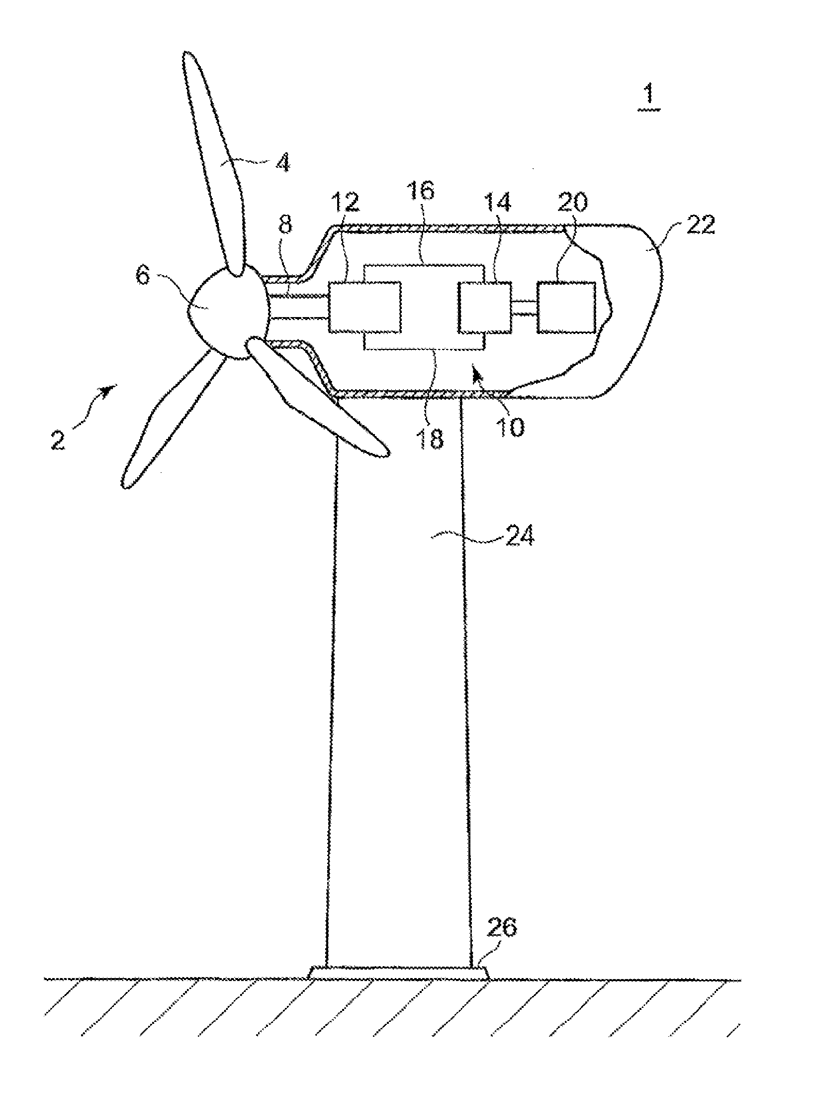
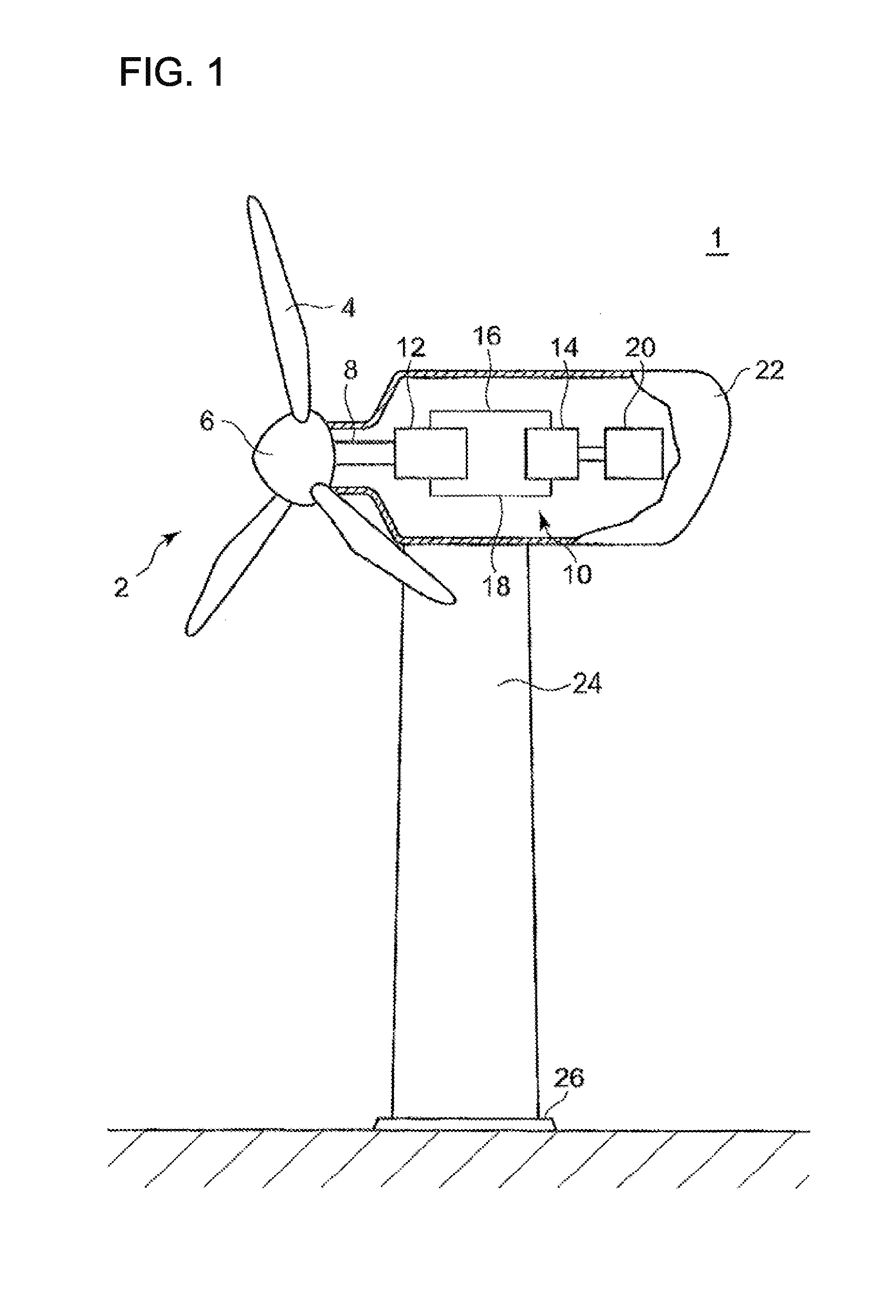
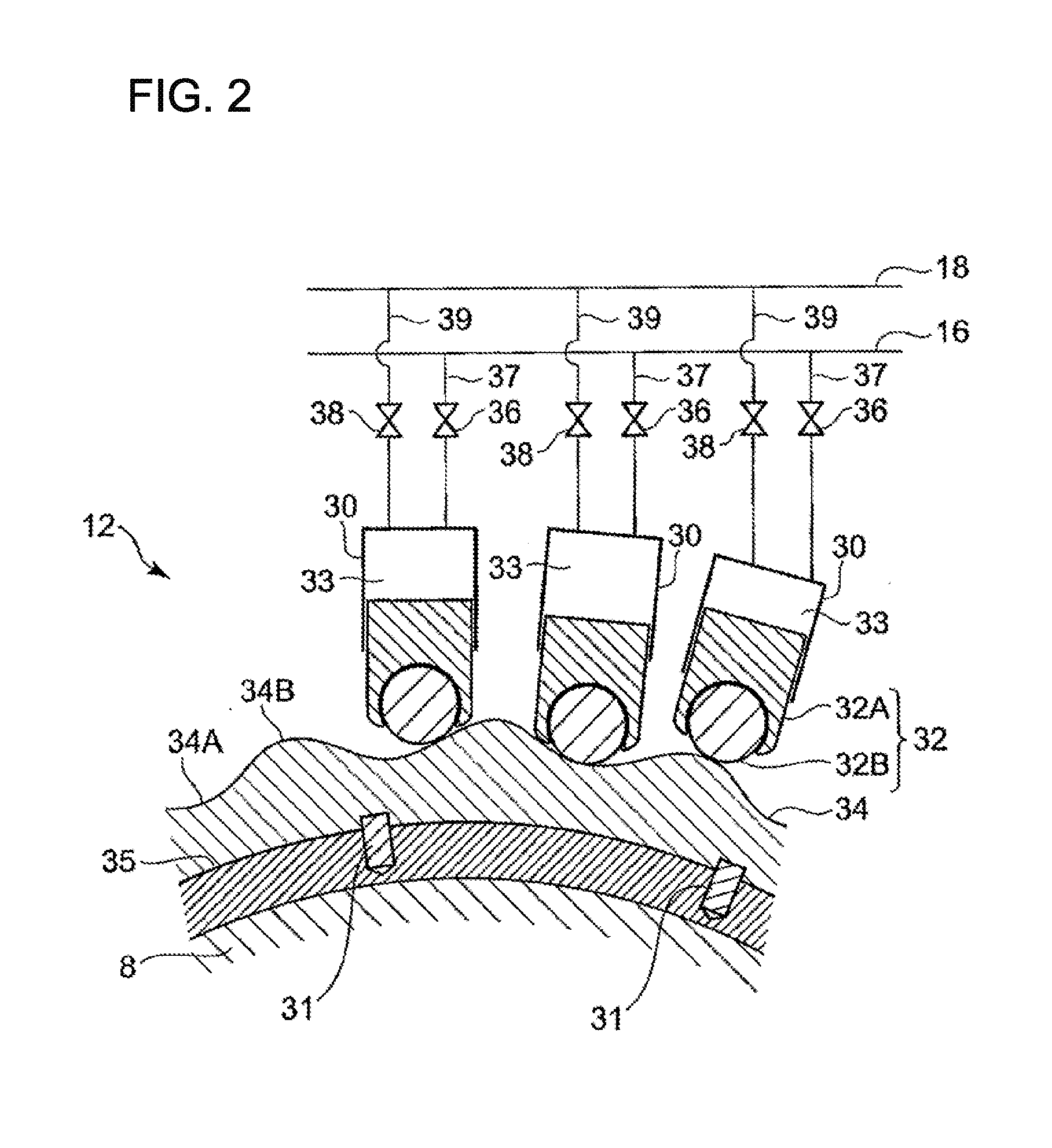
[0067]A general structure of the wind turbine generator in relation to the present invention is explained hereinafter. FIG. 1 is a schematic view showing an example structure of the wind turbine generator. FIG. 2 is a schematic view showing an example structure of the wind turbine generator. FIG. 2 is a view showing an example configuration of a hydraulic pump of the wind turbine generator. FIG. 3 is a view showing an example configuration of a hydraulic motor of the wind turbine generator.

[0068]As an example of the wind turbine generator, a three-bladed wind turbine is used. However, the present invention is not limited to this example and c...


PUM


Abstract

An object of the present invention is to provide a wind turbine generator and a tidal current generator equipped with a hydraulic transmission with a combination of a hydraulic pump and a hydraulic motor and which has a superior productivity and maintainability. The wind turbine generator 1 has the hydraulic transmission 10 for transmitting the rotation energy of a main shaft 8 to a generator 20. The hydraulic transmission 10 includes a hydraulic pump 12 of variable displacement type which is driven by the main shaft 8, a hydraulic motor 14 of variable displacement type which is connected to the generator 20, and a high pressure oil line and a low pressure oil line which are arranged between the hydraulic pump 12 and the hydraulic motor 14. The hydraulic transmission 10 is at least partially constituted of a plurality of modules (M1 to M7).

Description

TECHNICAL FIELD [0001]The present invention relates to a wind turbine generator and a tidal current generator which transmit rotation energy of a rotor to a generator via a hydraulic transmission that is a combination of a hydraulic pump and a hydraulic motor.BACKGROUND ART [0002]In recent years, from a perspective of preserving the environment, it is becoming popular to use a wind turbine generator utilizing wind power and a renewable energy type turbine generator such as a tidal current generator utilizing tidal.[0003]The wind turbine generator among above generators converts motion energy of the wind to the rotation energy of the rotor and further converts the rotation energy of the rotor to electric power by the generator. In a common wind turbine generator, the rotation speed of the rotor is about a few rotations per minute to tens of rotations per minute. Meanwhile, a rated speed of the generator is normally 1500 rpm or 1800 rpm and thus a mechanical gearbox is provided betwee...

Claims


Application Information

Patent Timeline
IPC IPC(8): F03D9/00
CPCF03D9/001F03D9/028F03D11/02F05B2260/406F16H39/02Y02E10/38Y02E10/28Y02E60/15Y02E10/722F03D9/17F03D9/25F03D9/28F03D15/00F03D15/20Y02E10/30Y02E10/72Y02E60/16Y02E70/30Y02P80/10Y02E10/20
Inventor TSUTSUMI, KAZUHISAMAEKAWA, ATSUSHISHIMIZU, MASAYUKISALTER, STEPHENSTEIN, UWERAMPEN, WILLIAMFOX, ROBERTKARSTENS, HAUKE
Owner MITSUBISHI HEAVY IND LTD
Learn More