Image processing apparatus, control method thereof, and computer program

Inactive Publication Date: 2012-03-15
CANON KK
View PDF2 Cites 62 Cited by
  • Summary
  • Abstract
  • Description
  • Claims
  • Application Information

AI Technical Summary

Benefits of technology

[0005]Also, the technique described in Japanese Patent Laid-Open No. 2007-325831 simply interpolates layers near a region back-projected onto a tomogram as a region where an artifact is more likely to be generated, but it does not calculate an original layer position by detecting intensity signals of a layer attenuated in the back-projected region. Furthermore, even when image correction is executed for the purpose of layer detection, since an artifact reg

Problems solved by technology

However, the technique described in Japanese Patent Laid-Open No. 2008-073099 does not disclose any method to calculate the layer position in a region where an artifact is generated.
Also, the technique described in Japanese Patent Laid-Open No. 2007-325831 simply

Method used


Image

  • Image processing apparatus, control method thereof, and computer program
  • Image processing apparatus, control method thereof, and computer program
  • Image processing apparatus, control method thereof, and computer program

Examples


first embodiment

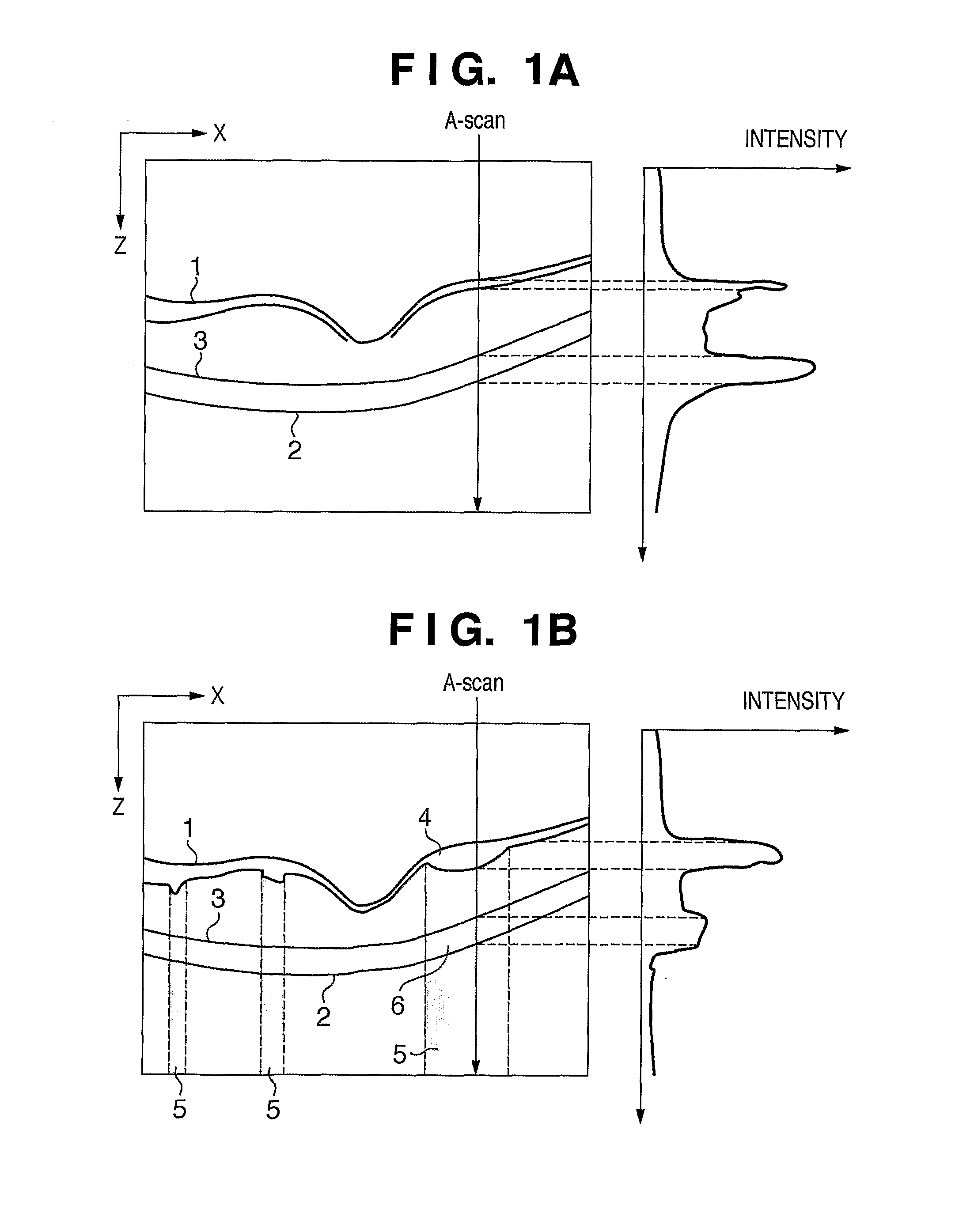
[0044]When an image of an eye to examined (an eye as an examination target) is to be captured by an OCT apparatus, if a blood vessel or exudate exists on a retina, since the intensity of measurement light lowers, a retinal pigment epithelium is attenuated on the obtained image, and it is difficult to detect the layer. Hence, in this embodiment, an artifact region is determined from a tomogram of an eye to be examined, and image correction is applied to that region according to a statistical amount in the region.

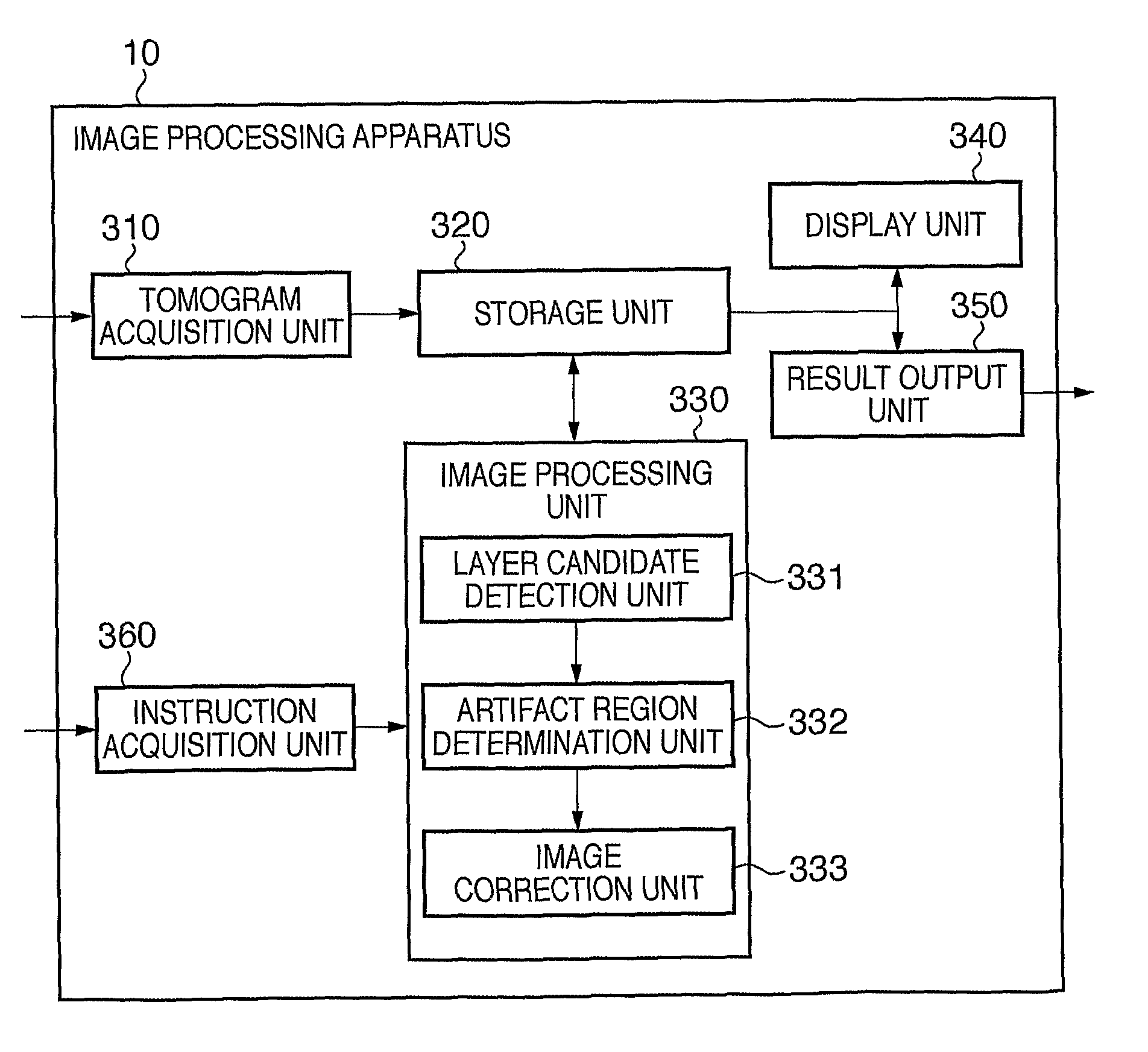
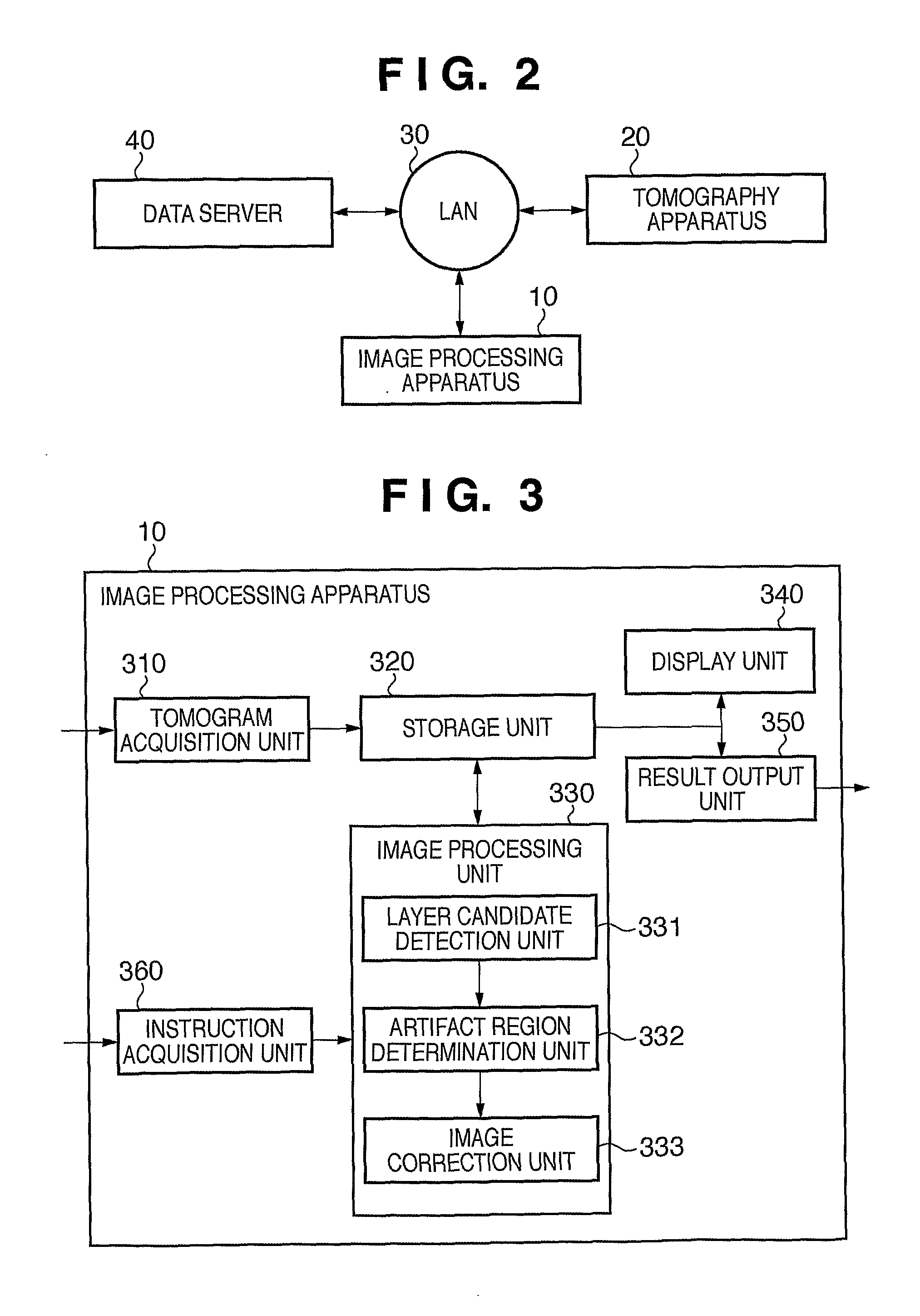
[0045]FIG. 2 is a block diagram showing the arrangement of apparatus connected to an image processing apparatus 10 according to this embodiment. As shown in FIG. 2, the image processing apparatus 10 is connected to a tomography apparatus 20 via an optical fiber and an interface of, for example, USB or IEEE1394. The tomography apparatus 20 is connected to a data server 40 via a local area network (LAN) 30 based on, for example, Ethernet®. Note that the image processing apparat...

second embodiment

[0092]In this embodiment, not only image correction is performed in an artifact region like in the first embodiment, but also a predetermined layer is detected from the corrected image. This embodiment applies image correction even to a region where an artifact is generated and intensities are attenuated, so as to facilitate detection of remaining edge information, and allows to calculate a more precise layer position by detecting that edge information.

[0093]Since the arrangement of apparatus connected to an image processing apparatus 10 according to this embodiment is the same as that in the first embodiment, a description thereof will not be repeated. FIG. 8 is a functional block diagram of the image processing apparatus 10 according to this embodiment. Referring to FIG. 8, an image processing unit 801 of this embodiment is different from the arrangement of the image processing unit 330 of the image processing apparatus 10 of the first embodiment in that a layer decision unit 334 ...

third embodiment

[0116]In this embodiment, in place of determination of an artifact region using only a tomogram in the first and second embodiments, a projection image is generated from a tomogram of an eye to be examined, and position information of tissue or a morbid portion extracted from the projection image is back-projected onto the tomogram, so as to narrow down artifact candidate regions in advance. In general, it is easier to calculate position information of an artifact region caused by, for example, a blood vessel (or bleeding) from a projection image than from only a tomogram. Hence, this embodiment will explain a case in which a blood vessel (bleeding) region is extracted from a projection image, that position information is mapped onto a tomogram, and an edge portion of an artifact region is searched for and specified around the mapped region, so as to calculate a range of the artifact region at higher precision.

[0117]Since the arrangement of apparatus connected to an image processing...


PUM


Abstract

The present invention an image processing apparatus, which processes an image of a tomogram obtained by capturing an image of an eye to be examined by a tomography apparatus, comprises, layer candidate detection means for detecting layer candidates of a retina of the eye to be examined from the tomogram, artifact region determination means for determining an artifact region in the tomogram based on image features obtained using the layer candidates, and image correction means for correcting intensities in the artifact region based on a determination result of the artifact region determination means and image features in the region.

Description

TECHNICAL FIELD[0001]The present invention relates to an image processing apparatus, control method thereof, and computer program.BACKGROUND ART[0002]Ophthalmic examinations are prevalently made for the purpose of earlier diagnoses of various diseases that are among the top reasons of lifestyle-related diseases and causes of blindness. A tomography apparatus for an eye portion such as an OCT (Optical Coherence Tomography) is expected to effectively give more adequate diagnoses of diseases since it allows to three-dimensionally observe the state of the interior of retina layers. By measuring a change in layer thickness of, for example, a nerve fiber layer or retina, and a change in layer geometry such as an unevenness of a retinal pigment epithelium from this tomogram, it is possible to quantitatively diagnose the degrees of progress of diseases such as glaucoma, macular edema, and age-related macular degeneration, and recovery levels after medical treatments. In order to quantitativ...

Claims


Application Information

Patent Timeline
IPC IPC(8): G06K9/00
CPCA61B5/0066A61B5/0073G06T7/0083G01B9/02083G06T2207/10101G01B9/02091G06T2207/30041A61B3/102G06T7/12A61B3/10A61B3/12G06T1/00
Inventor IMAMURA, HIROSHIKATAYAMA, AKIHIRO
Owner CANON KK
Why Eureka
Try Eureka