
System and Method for Reducing Angular Geometric Distortion in an Imaging Device

a technology of angular geometric distortion and imaging device, which is applied in the field of system and method for reducing angular geometric distortion in imaging device, can solve the problems of “backlash” of the transducer, the fluoroscopy system does not image the tissue of the vessel, and the image is compromised

Active Publication Date: 2012-03-15
VOLCANO CORP
View PDF0 Cites 8 Cited by
  • Summary
  • Abstract
  • Description
  • Claims
  • Application Information

AI Technical Summary

Benefits of technology

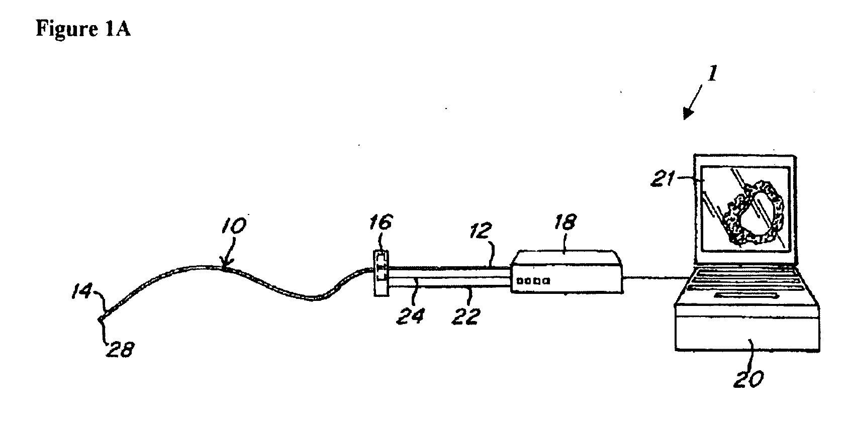
[0010]Embodiments of the invention are directed to a system and method for reducing angular geometric distortion in an imaging device. The system and method according to the invention may be utilized with any type of device used to image and / or inspect an interior portion of a cavity, such as a substantially tubular cavity, in which it is advantageous to significantly reduce or substantially eliminate angular geometric distortion.
[0011]Further, embodiments of the invention are directed to a system and method capable of significantly reducing or substantially eliminating NURD in both continuously rotated IVUS systems, in which the direction of rotation remains substantially constant, and in manually rotated IVUS systems, in which the direction of rotation is changed and windup and backlash NURD are also present.

Problems solved by technology

However, fluoroscopy systems do not image the vessel tissue, but rather the blood pool inside the vessel lumen.
However, these images are compromised in that the assumed angular orientation of the ultrasonic transducer at the distal tip of the catheter is not, in fact, the actual orientation of the transducer.
However, this change in rotational direction leads to another form of NURD caused by the “windup” and resulting “backlash” of the transducer when the rotational direction is changed.
However, this comes at the expense of increased transducer, catheter, and imaging system complexity and cost.

Method used


Image

  • System and Method for Reducing Angular Geometric Distortion in an Imaging Device
  • System and Method for Reducing Angular Geometric Distortion in an Imaging Device
  • System and Method for Reducing Angular Geometric Distortion in an Imaging Device

Examples


Embodiment Construction

[0024]The following detailed description of embodiments of the invention is discussed in the context of NURD reduction for an IVUS system. However, the invention may be utilized with any type of device used to image and / or inspect an interior portion of a cavity, such as a substantially tubular cavity, in which it is advantageous to significantly reduce or substantially eliminate angular geometric distortion.

[0025]NURD reduction for an IVUS system can be viewed as a process that more accurately assigns angles that are associated with each acoustic line in an IVUS frame compared to angles that are assumed to be present at a proximal end of a catheter as imaging data is collected. The systems and methods according to certain embodiments of the invention apply algorithms which may be implemented in either hardware or software, and may operate in real time on data as it is collected from a transducer to produce images without any objectionable distortions caused by NURD.

[0026]It should ...


PUM


Abstract

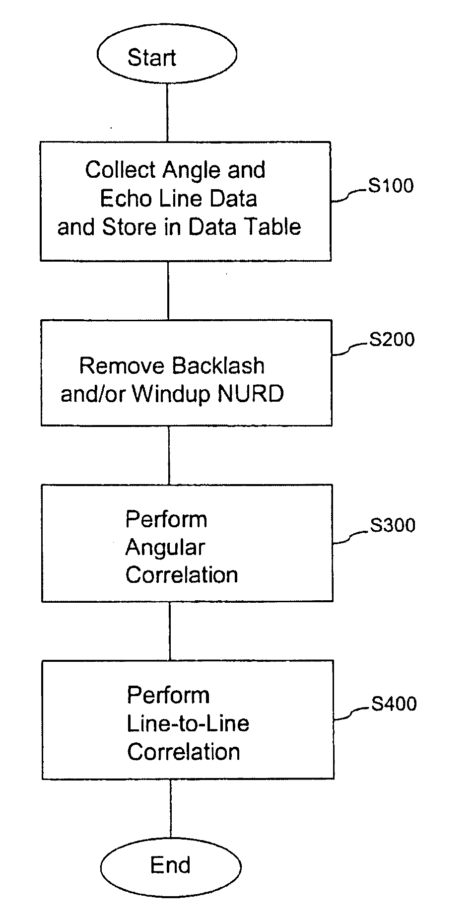
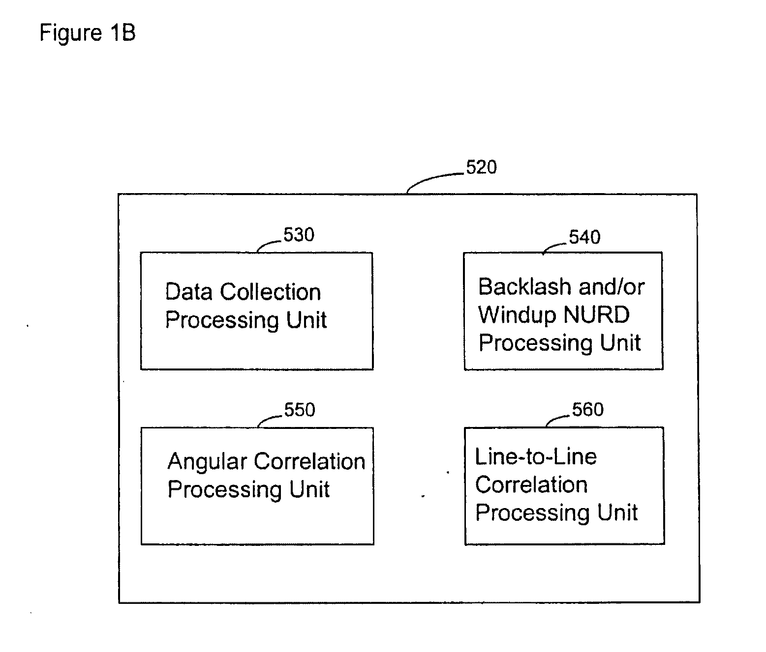
A system and method are provided for significantly reducing or substantially eliminating angular geometric distortions in devices designed for imaging and / or inspection of an interior portion or surface of a cavity. A series of processing steps or methods may be employed to eliminate Non-Uniform Rotational Distortion (NURD) in such devices, for example, unidirectional and bi-directional intravascular ultrasonic (IVUS) imaging systems. The system may include a processor and an electronic module which control operation of a transducer assembly provided at a distal end of a catheter assembly. The system invokes a first processing step or method to collect and store raw angle and line data, as well as one or more of second and third processing steps or methods which adjust for NURD experienced during backlash of a bi-directional imaging system and a fourth processing step or method which performs a line-to-line correlation function.

Description

BACKGROUND OF THE INVENTION[0001]1. Field of the Invention[0002]This invention relates to a system and method for reducing angular geometric distortion in an imaging device.[0003]2. Background of the Related Art[0004]A number of diagnostic tools are used in the field of Interventional Cardiology to diagnose and treat heart disease. Among other things, Intravascular Ultrasonic (IVUS) imaging systems are used to estimate an extent of coronary artery plaque, allowing an interventionalist to detect heart disease, estimate the severity of the disease and its effect on blood flow, and choose appropriate therapies. One such system is a fluoroscopy system, which injects a radio-opaque contrast dye into the bloodstream, and then uses a real time x-ray imaging technique to watch as the contrast dye passes through the vascular tree. However, fluoroscopy systems do not image the vessel tissue, but rather the blood pool inside the vessel lumen.[0005]In an attempt to obtain an image of the vessel...

Claims


Application Information

Patent Timeline
Patent Type & Authority Applications(United States)
IPC IPC(8): A61B8/12A61B8/00
CPCA61B8/12A61B5/0066A61B8/5276
Inventor GOODNOW, JOHN W.MAGNIN, PAUL A.
Owner VOLCANO CORP
Learn More