
Memory Architecture with Policy Based Data Storage

a data storage and memory architecture technology, applied in the field of computer memory management, can solve the problems of less efficient use of memory space, lower latency, and increased overall latency, and achieve the effect of efficient storag

Inactive Publication Date: 2012-03-15
IBM CORP
View PDF4 Cites 38 Cited by
  • Summary
  • Abstract
  • Description
  • Claims
  • Application Information

AI Technical Summary

Benefits of technology

[0005]In certain embodiments a memory or an I / O controller receives a write request where the data to be written is associated with an address. Hint information for determining where; i.e., which type or class of memory to write data, may be associated with the address and may relate to memory characteristics such as an historical, O / S direction, data priority, job priority, job importance, job category, memory type, I / O sender ID, latency, power, write cost, or read cost components. The memory controller may interrogate the hint information to determine where (e.g., what memory type) to store the associated data. Data is therefore efficiently stored within the system in the memory type or class most appropriate based on the hint information. The hint information may also be used to track post-write information and may be interrogated to determine if a data migration should occur and to which new memory type the data should be moved.

Problems solved by technology

However, different parts of a computer's memory space exhibit different memory latencies or the amount of time it takes for data to be transferred from a memory location to the entity that requested it.
However, sometimes certain portions of a relatively slower memory type may actually have a lower latency than portions of a relatively faster memory type.
Placing frequently used, highly important, etc, data units in a slower portion of the faster memory type instead of the faster portion of the slower memory type may result in a less efficient usage of memory space that may result in greater overall latency, higher total power consumption, etc.

Method used


Image

  • Memory Architecture with Policy Based Data Storage
  • Memory Architecture with Policy Based Data Storage
  • Memory Architecture with Policy Based Data Storage

Examples


Embodiment Construction

[0030]For a better understanding of the various embodiments, together with other and further features and advantages thereof, reference is made to the following description, taken in conjunction with the accompanying drawings and asserted in the claims.

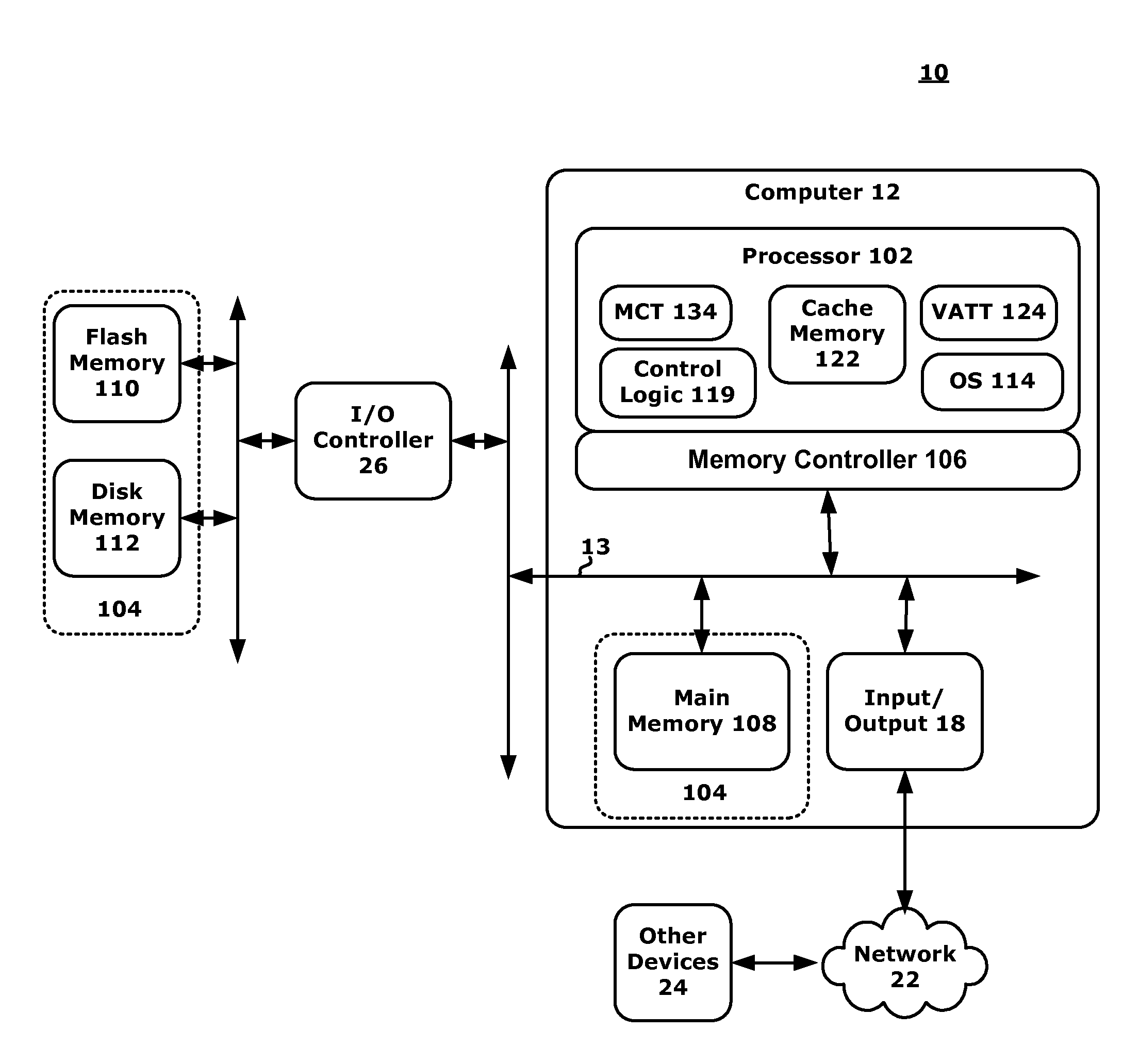
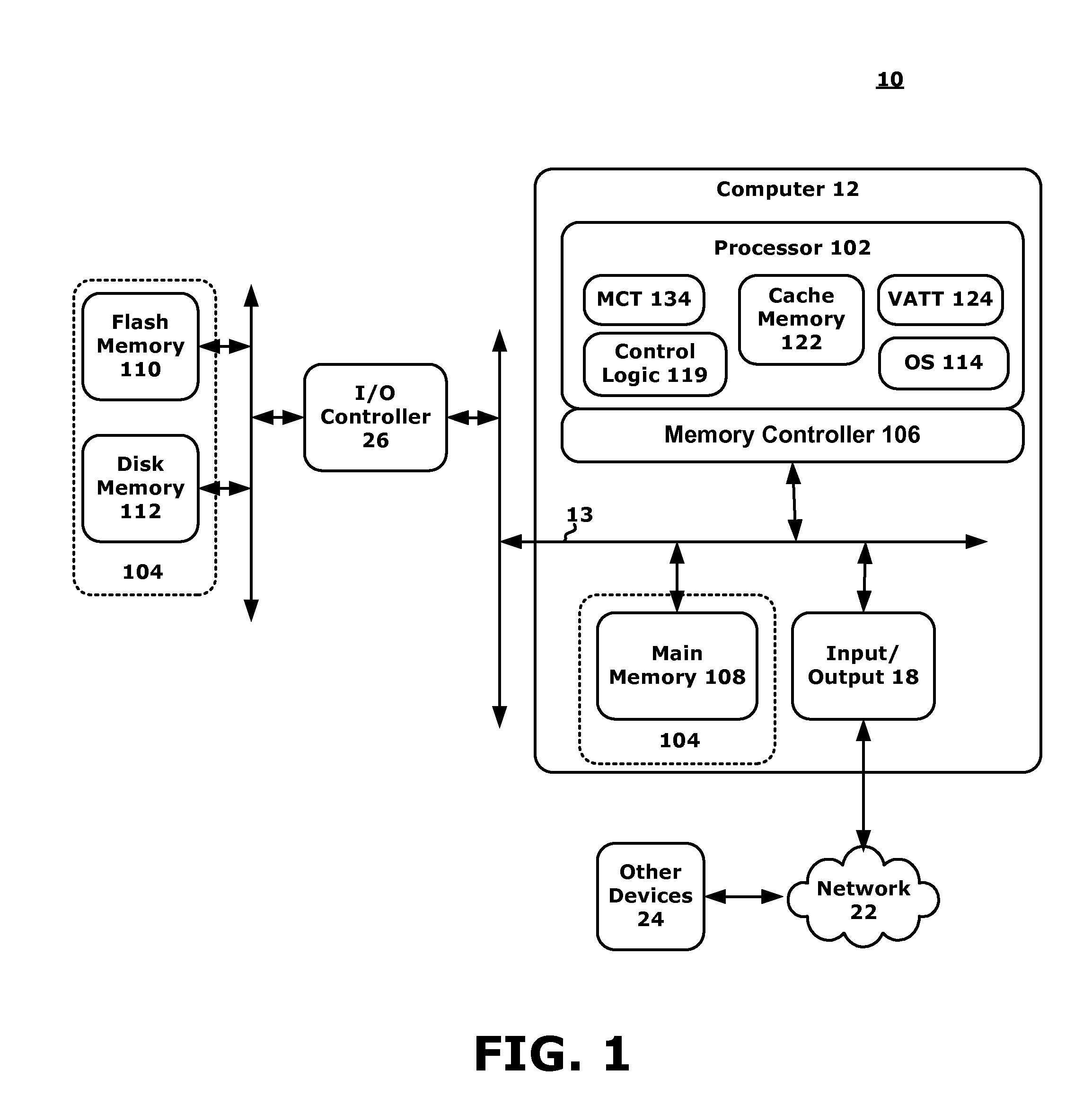
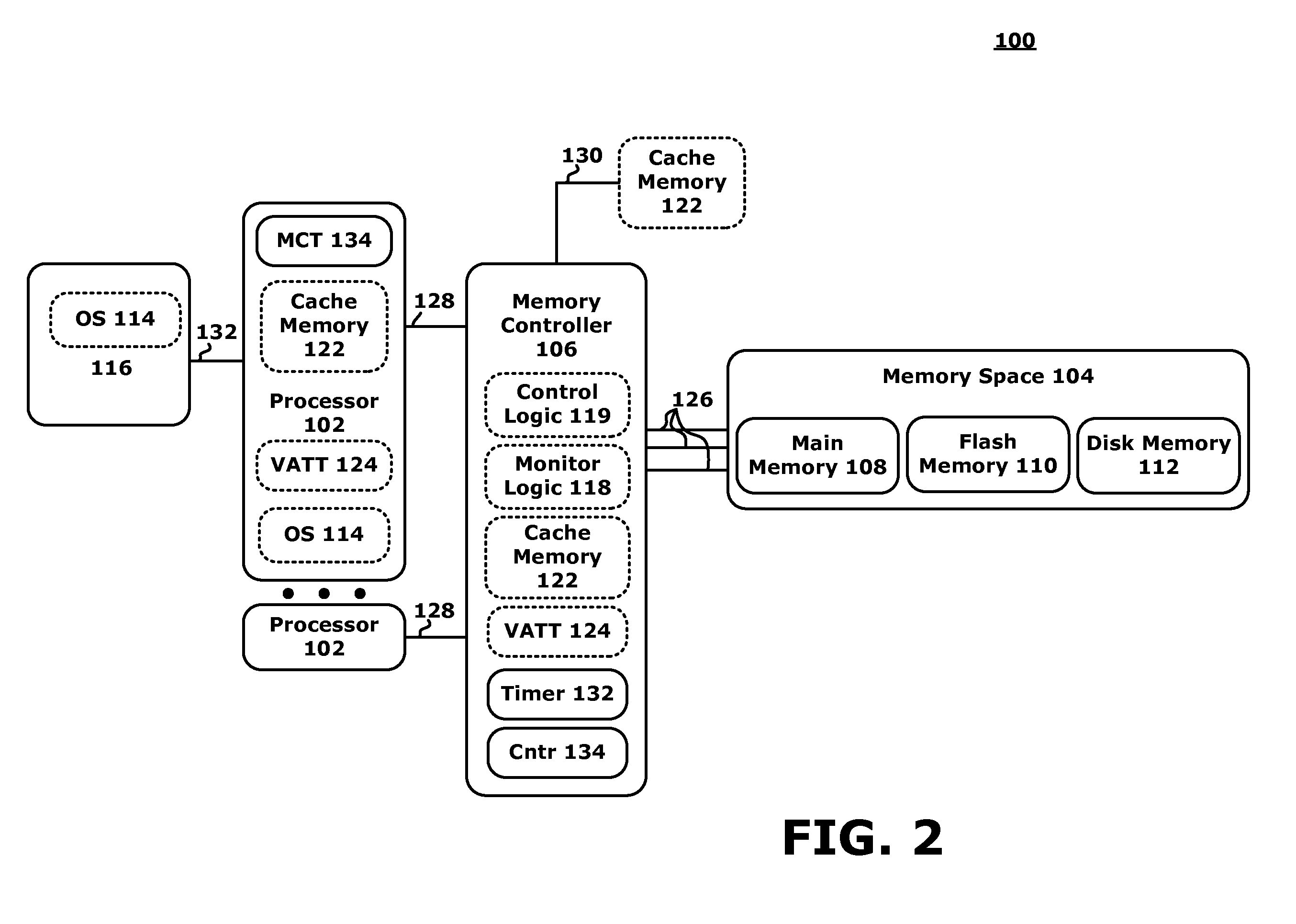
[0031]It will be readily understood that components or embodiments, as generally described and illustrated in the FIGs. herein, may be arranged and designed in a wide variety of different configurations. Thus, the following more detailed description of the embodiments of the apparatus, system, and method, as represented in FIGS. 1 through 15, are not intended to limit the scope as claimed, but are merely representative of selected exemplary embodiments.

[0032]As will be appreciated by one skilled in the art, various embodiments may be embodied as a system, method, computer program product or any combination thereof. Accordingly, embodiments may take the form of an entirely hardware embodiment, an entirely software embodiment (including...


PUM


Abstract

A computing system and methods for memory management are presented. A memory or an I / O controller receives a write request where the data two be written is associated with an address. Hint information may be associated with the address and may relate to memory characteristics such as an historical, O / S direction, data priority, job priority, job importance, job category, memory type, I / O sender ID, latency, power, write cost, or read cost components. The memory controller may interrogate the hint information to determine where (e.g., what memory type or class) to store the associated data. Data is therefore efficiently stored within the system. The hint information may also be used to track post-write information and may be interrogated to determine if a data migration should occur and to which new memory type or class the data should be moved.

Description

FIELD OF THE INVENTION[0001]Embodiments relate to computer memory management and, more specifically, to organizing data in a memory system having differing memory types or classes of memory.DESCRIPTION OF THE RELATED ART[0002]Virtually all computer circuits employ some sort of digital memory to store data. Such memory can include a combination of different types of memory devices, including one or more of the following: on-chip memory (such as array of registers), on board memory (such as cache memory), main memory (such as DRAM memory chips on a different circuit board from a processor), flash memory, and disk memory (such as a hard drive).[0003]Some data units (which can include any method of grouping data) residing in a memory space are less-used than other data units stored on the same memory space. However, different parts of a computer's memory space exhibit different memory latencies or the amount of time it takes for data to be transferred from a memory location to the entit...

Claims


Application Information

Patent Timeline
IPC IPC(8): G06F12/10G06F12/00
CPCG06F12/06Y02B60/1225G06F12/10G06F13/1694Y02D10/00
Inventor TREMAINE, ROBERT B.WISNIEWSKI, ROBERT W.
Owner IBM CORP
Learn More