Panel, in particular a floor panel

a floor panel and floor technology, applied in the field of floor panels, can solve the problems of increased costs, increased costs, and relatively high production costs, and achieve the effects of increasing rigidity, simple and cost-effective production, and increasing the stability of the connection

Active Publication Date: 2012-03-22
VÄLINGE INNOVATION AB
View PDF0 Cites 55 Cited by
  • Summary
  • Abstract
  • Description
  • Claims
  • Application Information

AI Technical Summary

Benefits of technology

[0014]Firstly, the production is considerably simplified through this embodiment. The adjustment of the tolerances of different components is omitted. Production times and costs are reduced, because it is not necessary to assemble and join different components. For the end user, it is furthermore ensured that no components are missing and work cannot be continued.
[0015]Another advantage lies in that due to the laying of the spring element on the lower locking section, the horizontal slot to expose the spring element from the core is omitted. The moveable spring element can thus have a greater vertical extension, whereby the rigidity and strength of the panel connection is improved. Furthermore, the greater vertical extension of the moveable spring element compared to the board thickness renders possible a secure connection of thin panels with board thicknesses of approx. 4 mm to 8 mm.
[0018]According to the invention, it is provided that the essentially vertical slot is formed at least in part through the lower locking section. This means that the slot does not need to be embodied over the entire length as a cutout, but can be embodied at its ends as a gap in particular in transition areas. The gap in the transition area is expediently opened towards the underside of the panel and closed towards the top side of the panel. This renders possible a simple and cost-effective production, because the panel can be moved at a constant speed over a milling tool and only the penetration depth of the milling tool into the panel needs to be changed. A transition area can be embodied on one or on both ends of the spring element. The gap can have a variable depth, for example, a uniformly increasing depth.
[0019]Preferably the essentially vertical slot is embodied in the area of the hook element of the lower locking section. In the area of the hook element, the locking section expediently has a maximum vertical extension, so that in this area the spring element can be embodied with a correspondingly large vertical extension. With increasing vertical extension of the spring element, the rigidity thereof is also increased.
[0020]When a plurality of spring elements spaced apart from one another is provided over the length of the side edge, the stability of the connection is increased, because the free spring deflection in the longitudinal direction of the spring element is limited. The spacing between the individual spring elements can be selected to be larger or smaller. The smaller the spacing, the greater the effective area with which the locking is carried out of course, so that the transferable forces in the vertical direction are correspondingly high.

Problems solved by technology

Special injection molds are necessary for the production of this spring element, so that the production is relatively expensive.
Furthermore, a high-quality plastic must be used in order to provide sufficient strength values, which makes the spring element even more expensive.
Additional expenses result because the locking element is embodied as a separate component.
The production of the locking element is carried out for technological reasons spatially separately from the panels, so that an integration into the continuous production process, in particular for floor panels, is likely to be impossible.
Through the different materials, wood material on the one hand and plastic on the other hand, the adjustment of production tolerances from two separate production processes is complex and cost-intensive.
Since the locking in the vertical direction would be ineffective if the locking element was missing, in addition this must be secured from falling out of the groove inserted in the side edge in the further production process and during transport.
This securing is also complex.
Furthermore, it cannot be ruled out that the do-it-yourselfer upon placing the spring element makes a mistake that means that precise locking is not possible and the bond separates over time, which is then wrongly attributed by the consumer to the quality supplied by the manufacturer.
However, this inevitably means that only low, vertically aligned forces can be absorbed, so that production must be carried out with extremely low tolerances, in order to ensure that the connection does not spring open with normal stress in the case of even slight irregularities in the floor and / or soft subfloors.
However, this locking is not suitable for thinner panels with a board thickness of approx.

Method used


Image

  • Panel, in particular a floor panel
  • Panel, in particular a floor panel
  • Panel, in particular a floor panel

Examples


Embodiment Construction

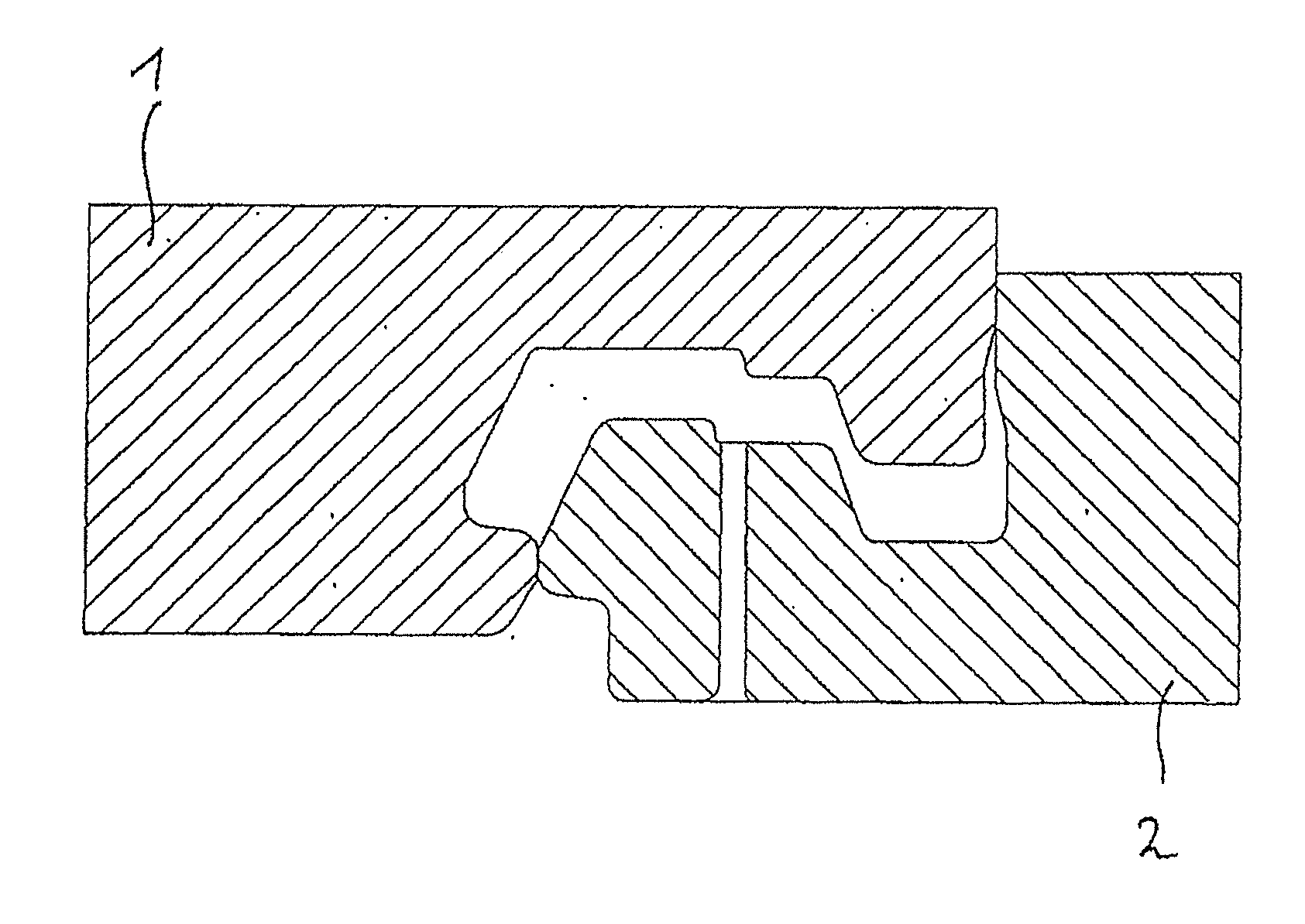
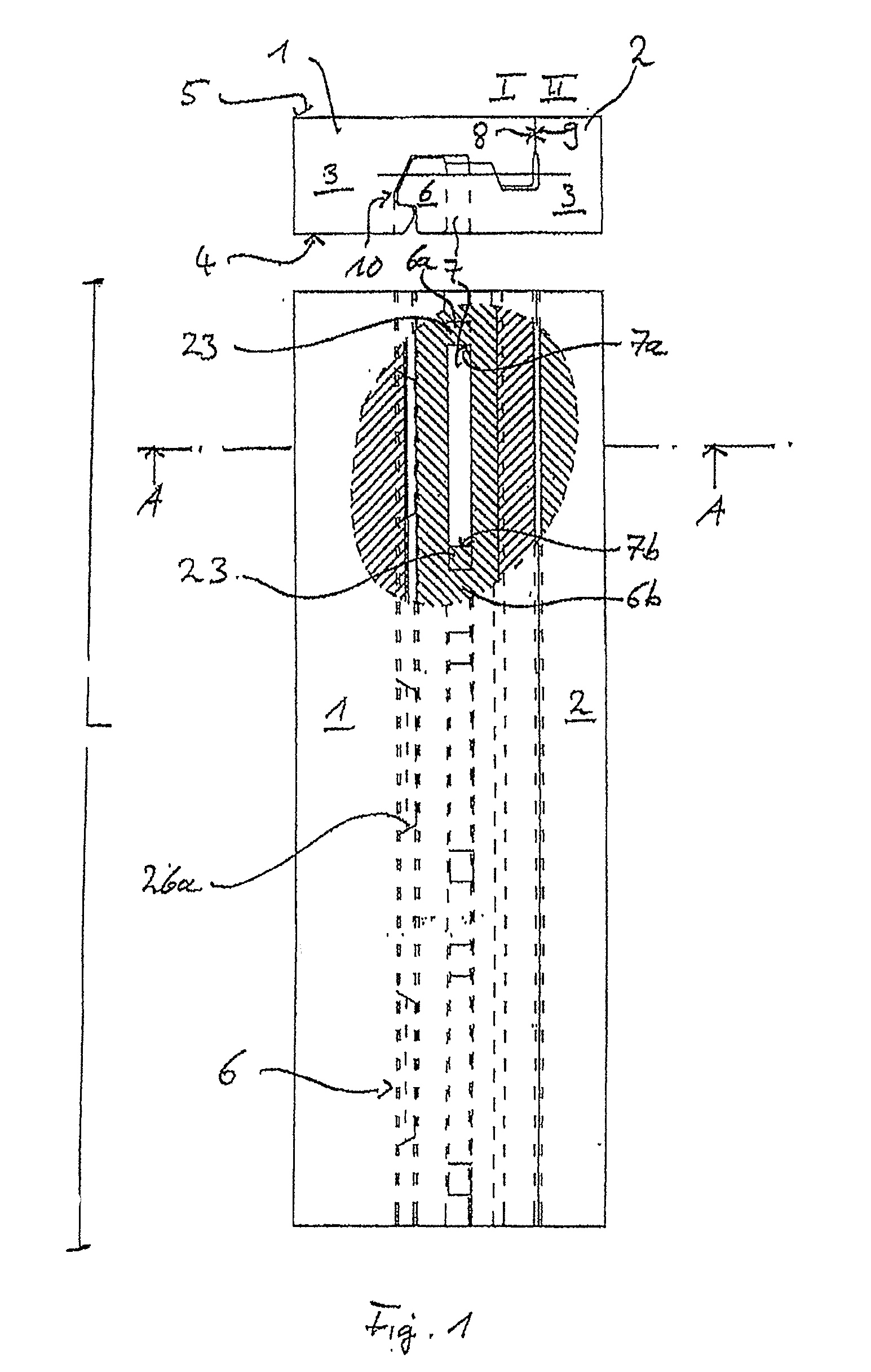
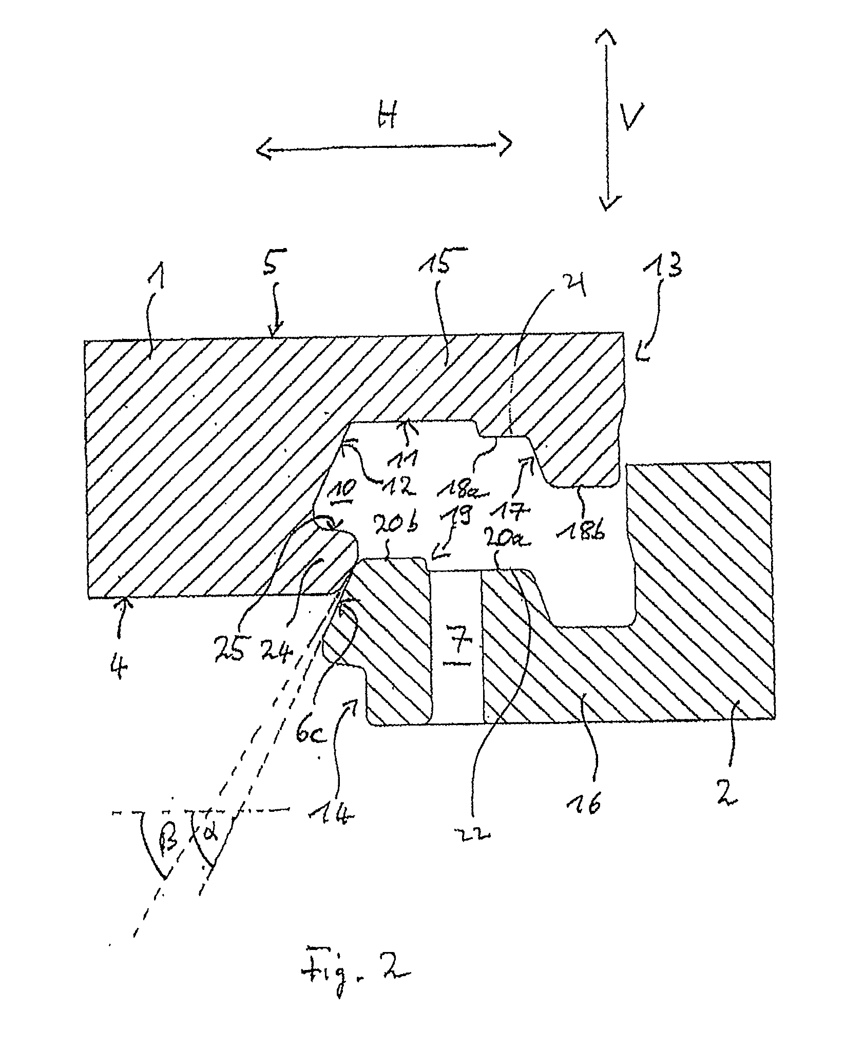
[0028]The panels 1, 2 are embodied identically. They comprise a core 3 of wood material or a wood material / plastic mixture. The panels 1, 2 are profiled on their side edges I, II lying opposite one another, wherein the side edge I of the underside 4 and the side edge II of the top side 5 have been machined by milling.

[0029]Three spring elements 6 are embodied on the side edge II. The spring elements 6 are identical, so that one of the spring elements 6 is described by way of example below. However, it is not necessary for the tongue elements 6 to be embodied identically.

[0030]The spring element 6 was produced by milling out the core 3, in that a slot 7 with ends 7a, 7b running essentially vertically was milled. The side edges I, II have the length L. In the longitudinal direction of the side edge II, the spring element 6 is connected to the core material with its ends 6a, 6b. The milling out of the spring element 6 from the core 3 is carried out exclusively through the slot 7. The o...


PUM


Abstract

A method of forming a panel having a core of a wood material or wood material / plastic mixture and a top side and an underside is provided. The method includes forming a profile corresponding to one another on at least a first side edge and a second side edge lying opposite one another. The method further includes forming a hook connection with an upper locking section having a hook element and a lower locking section having a hook element which effects the locking in the horizontal direction, and forming at least one spring element movable in the horizontal direction which effects the locking in the vertical direction (V). The at least one spring element is free in the direction of the first side edge lying opposite by an essentially vertical slot. In the method of manufacturing, the panel is moved at a constant speed when the essentially vertical slot is formed.

Description

CROSS REFERENCE TO RELATED APPLICATIONS[0001]The present application is a continuation application of copending application Ser. No. 12 / 440,137, filed on June. 22, 2009, which is a national stage filing under 35 U.S.C. 371 of PCT / EP2008 / 007328, filed on Sep. 8, 2008, all of which claim priority to German application serial no. 10 2007 042 840.7, filed on Sep. 10, 2007, the contents of each being incorporated by reference herein in their entireties.BACKGROUND OF THE INVENTION[0002]1. Field of the Invention[0003]The invention relates to a panel, in particular a floor panel, with a core of a wood material or wood material / plastic mixture, a top side and an underside, wherein the panel has a profile corresponding to one another on at least two side edges lying opposite one another, such that two identically embodied panels can be joined and locked to one another through an essentially vertical joining movement in the horizontal and vertical direction. The locking in the horizontal direc...

Claims


Application Information

Patent Timeline
Patent Type & Authority Applications(United States)
IPC IPC(8): B27M3/04B27C5/00
CPCE04F15/02E04F15/04E04F2201/0146E04F2201/041E04G23/006Y10T428/167
Inventor BRAUN, ROGER
Owner VÄLINGE INNOVATION AB
Why Eureka
Try Eureka