
Thermal energy storage using supercritical fluids

a technology of supercritical fluids and energy storage systems, applied in indirect heat exchangers, lighting and heating apparatus, chemical production, etc., can solve the problems of relatively poor thermal conductance across solid pcm regions, large storage of heat, and heat transfer characteristics of pcms, so as to reduce the required volume, high energy density storage, and compressibility high

Inactive Publication Date: 2012-03-22
CALIFORNIA INST OF TECH
View PDF11 Cites 20 Cited by
  • Summary
  • Abstract
  • Description
  • Claims
  • Application Information

AI Technical Summary

Benefits of technology

[0019]A thermal energy storage system is described employing latent heat storage of a supercritical fluid instead of typical phase change materials. Two fundamental thermodynamic concepts are invoked. First, by using the latent heat of liquid/vapor phase change, high energy density storage is feasible. Second, by operating the thermal energy storage system at a higher pressure, the sa

Problems solved by technology

In terms of cost, cost of the storage material itself, heat exchanger for charging and discharging the system and the cost for the space and the enclosure for the thermal energy storage are the important factors.
The cost of such a system depends on the storage fluid cost.
In contrast, phase change materials (PCMs) rely on the latent heat energy and can therefore store very large amounts of heat.
The DOE had studied the possibility of using PCM for heat storage in the 1980's, but did not pursue it further primarily due to the complexities of the required system and the operational uncertainty over lifetime of the PCMs.
Additionally, the heat transfer characteristics for PCMs have two major problems.
They have relatively poor thermal conductance across regions of solid PCM compared to convective heat transfer in the heat transfer fluid (HTF).
In addition, there is a “pinch-point” problem which refers to the relatively small temperature differences between the PCM and the charging or discharging HTF which occurs in the heat exchanger where the PCM is just dropping below or rising above the phase change temperature.
However, the proposed technologies were either sensible heat-based approaches or very advanced technologies, where it is not clear whether such technologies will deliver adequate low-cost energy storage.

Method used


Image

  • Thermal energy storage using supercritical fluids
  • Thermal energy storage using supercritical fluids
  • Thermal energy storage using supercritical fluids

Examples


Embodiment Construction

[0034]1. Overview

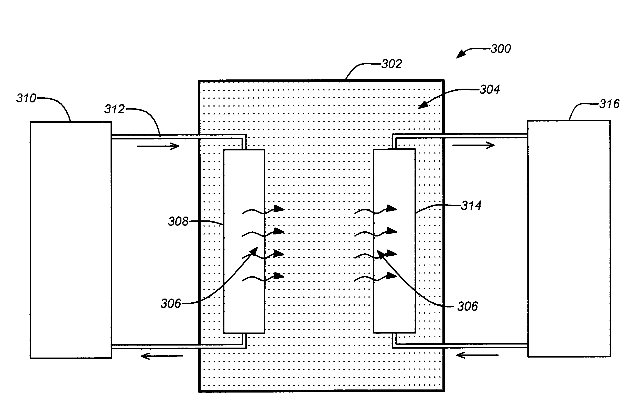
[0035]A new thermal energy storage system has been proposed using pressurized supercritical fluids, which provides numerous advantages including a simpler system design, much lower fluid storage costs, improved system performance overall. Working with high temperature HTF and thermal storage yields higher system performance.

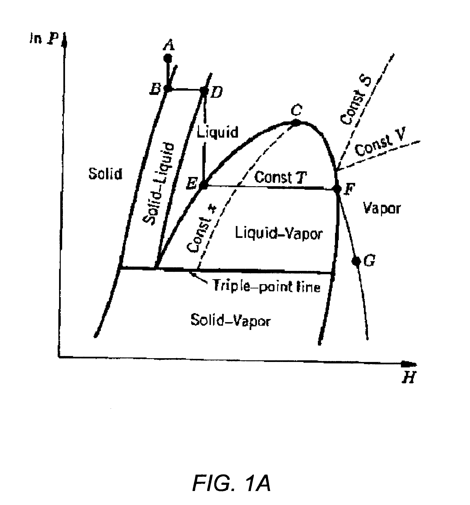
[0036]The thermal energy storage system may be described as employing latent heat storage of a supercritical fluid instead of typical phase change materials. Two fundamental thermodynamic concepts are invoked. First, by using the latent heat of liquid / vapor phase change, an efficient system is developed which will provide a constant sink / source of heat. Second, by operating the thermal energy storage system at a higher pressure, the saturation temperature is increased to operate at molten salt temperatures and above.

[0037]As previously mentioned, a thermal energy storage system may be described where a storage fluid remains in a supercritical sta...


PUM


Abstract

A thermal energy storage system is described employing latent heat storage of a supercritical fluid instead of typical phase change materials. Two fundamental thermodynamic concepts are invoked. First, by using the latent heat of liquid / vapor phase change, high energy density storage is feasible. Second, by operating the thermal energy storage system at a higher pressure, the saturation temperature is increased to operate at molten salt temperatures and above. Beyond the two-phase regime, supercritical operation permits capturing and utilizing heat taking advantage of latent and sensible heat, both in the two-phase regime as well as in supercritical regime while at the same time, reducing the required volume by taking advantage of the high compressibilities.

Description

CROSS-REFERENCE TO RELATED APPLICATIONS[0001]This application claims the benefit under 35 U.S.C. §119(e) of the following U.S. provisional patent application, which is incorporated by reference herein:[0002]U.S. Provisional Patent Application No. 61 / 384,635, filed Sept. 20, 2010, and entitled “Thermal Energy Storage with Supercritical Fluids”, by Ganapathi (Attorney Docket CIT-5441-P2).STATEMENT OF GOVERNMENT RIGHTS[0003]The invention described herein was made in the performance of work under a NASA contract, and is subject to the provisions of Public Law 96-517 (35 USC 202) in which the Contractor has elected to retain title.BACKGROUND OF THE INVENTION[0004]1. Field of the Invention[0005]This invention relates to thermal energy storage systems. Particularly, this invention relates to thermal energy storage systems using supercritical fluids as the storage medium.[0006]2. Description of the Related Art[0007]Solar thermal power (also referred to as Concentrated Solar Power [CSP]) is ...

Claims


Application Information

Patent Timeline
IPC IPC(8): F28D15/00
CPCY02E60/145F28D20/021C09K5/04F28D2020/0047Y02E60/14Y02P20/54
Inventor GANAPATHI, GANI B.
Owner CALIFORNIA INST OF TECH
Learn More