Wireless power supply apparatus

a power supply apparatus and wireless technology, applied in the direction of circuit arrangement, inductance, transmission, etc., can solve the problem of small power use efficiency, and achieve the effect of increasing the number of circuit components

Inactive Publication Date: 2012-03-22
ADVANTEST CORP
View PDF4 Cites 60 Cited by
  • Summary
  • Abstract
  • Description
  • Claims
  • Application Information

AI Technical Summary

Benefits of technology

[0011]The present invention has been made in order to solve such a problem. Accordingly, it is an exemplary purpose of the present invention to provide a wireless power supply system having an advantage of suppressing an increase in the number of circuit components.

Problems solved by technology

However, the power use efficiency thereof is small.

Method used


Image

  • Wireless power supply apparatus
  • Wireless power supply apparatus
  • Wireless power supply apparatus

Examples


first embodiment

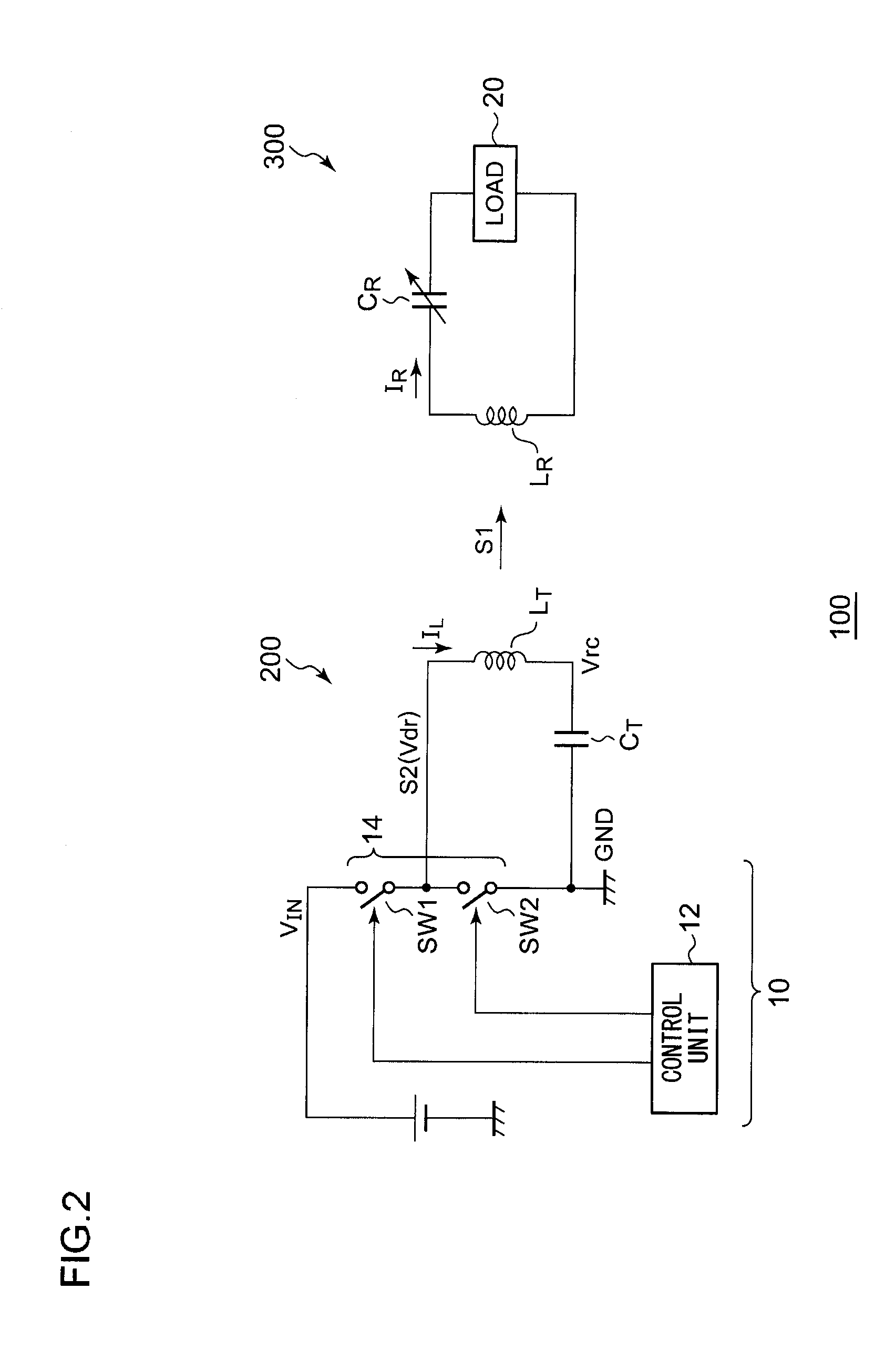
[0039]FIG. 2 is a circuit diagram which shows a configuration of a wireless power supply system 100 according to a first embodiment. The wireless power supply system 100 includes a wireless power supply apparatus 200 and a wireless power receiving apparatus 300.

[0040]First, description will be made regarding the configuration of the wireless power receiving apparatus 300. The wireless power receiving apparatus 300 receives an electric power signal S1 transmitted from the wireless power supply apparatus 200. The wireless power receiving apparatus 300 includes a reception coil LR, a resonance capacitor CR, and a load circuit 20. The resonance capacitor CR is arranged such that it and the reception coil LR form a resonance circuit. The resonance frequency of the resonance circuit is tuned to the electric power signal S1.

[0041]The reception coil LR receives the electric power signal S1 from the wireless power supply apparatus 200. An induced current (resonance current) IR that correspon...

second embodiment

[0064]Description has been made in the first embodiment regarding the power supply apparatus. Description will be made in the second embodiment regarding a system formed by combining a power receiving apparatus with a power supply apparatus according to the first embodiment, or regarding a power receiving apparatus which can be used as a stand-alone apparatus.

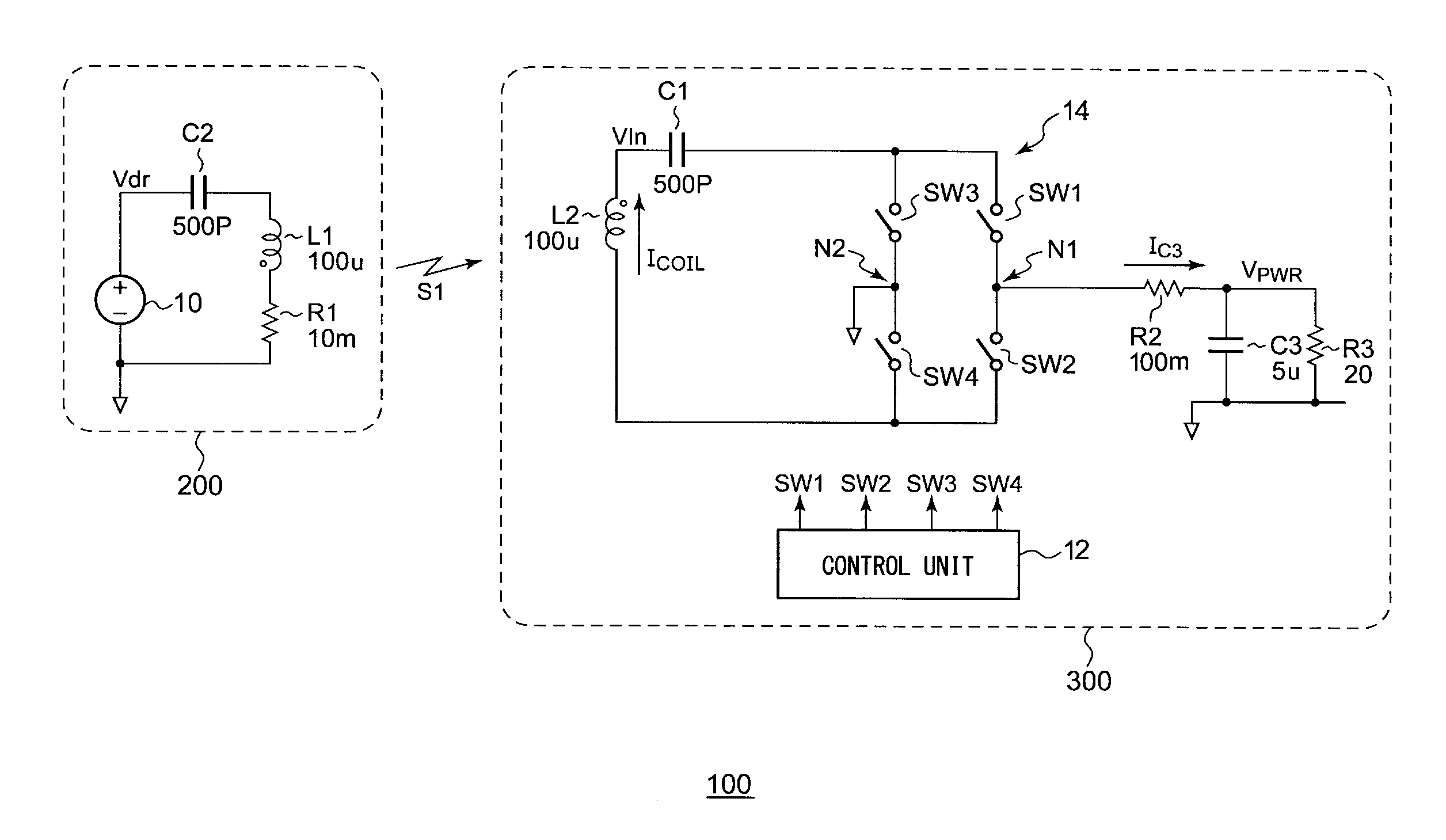
[0065]FIG. 8 is a circuit diagram which shows a configuration of a wireless power supply system 100 according to a second embodiment. In this circuit diagram, circuit constants are shown for exemplary purposes. However, such circuit constants are not intended to limit the present invention. The wireless power supply system 100 includes a wireless power supply apparatus 200 and a wireless power receiving apparatus 300. First, description will be made regarding the configuration of the wireless power supply apparatus 200.

[0066]The wireless power supply apparatus 200 transmits an electric power signal to the wireless power receivi...


PUM


Abstract

A wireless power supply apparatus transmits an electric power signal including any one of an electric field, a magnetic field, and an electromagnetic field. A bridge circuit includes multiple switches. A control unit performs switching control of the multiple switches of the bridge circuit at a first frequency configured as a transmission frequency. A transmission coil and a resonance capacitor form a resonance antenna, which is connected to the bridge circuit. The resonance frequency of the resonance antenna thus formed is a second frequency that is equal to or higher than the first frequency. A control unit is configured to be capable of adjusting the length of the dead time during which the multiple switches are all turned off at the same time.

Description

BACKGROUND OF THE INVENTION[0001]1. Field of the Invention[0002]The present invention relates to a wireless power supply technique.[0003]2. Description of the Related Art[0004]In recent years, wireless (contactless) power transmission has been receiving attention as a power supply technique for electronic devices such as cellular phone terminals, laptop computers, etc., or for electric vehicles. Wireless power supply transmission can be classified into three principal methods using an electromagnetic induction, an electromagnetic wave reception, and an electric field / magnetic field resonance.[0005]The electromagnetic induction method is employed to supply electric power at a short range (several cm or less), which enables electric power of several hundred watts to be transmitted in a band that is equal to or lower than several hundred kHz. The power use efficiency thereof is on the order of 60% to 98%. In a case in which electric power is to be supplied over a relatively long range ...

Claims


Application Information

Patent Timeline
Patent Type & Authority Applications(United States)
IPC IPC(8): H02J17/00
CPCH02J5/005H02J50/12H02J50/50H02J50/005H04B5/0037H04B5/0081
Inventor ENDO, YUKIFURUKAWA, YASUO
Owner ADVANTEST CORP
Why Eureka
Try Eureka