Tuning Circuit For Pivotal Antenna

a technology of pivotal antenna and tuning circuit, which is applied in the direction of pivotable antennas, antenna details, antennas, etc., can solve the problems of affecting the transmission efficiency of wireless signals, reducing the antenna gain and signal intensity, and generating null points of radiation patterns, so as to maintain the efficiency and stability of signal transmission, increase the antenna gain and signal intensity, and superior impedance and bandwidth

Inactive Publication Date: 2012-03-22
ADVANCED CONNECTEK INC
View PDF2 Cites 0 Cited by
  • Summary
  • Abstract
  • Description
  • Claims
  • Application Information

AI Technical Summary

Benefits of technology

[0006]One objective of the present invention is to provide a tuning circuit for a pivotal antenna, wherein a chip of an impedance-matching tuning circuit is integrated with a metal-plate element of a pivotal wireless device to make the radiation conductor of the antenna have superior impedance and bandwidth, and increase the antenna gain and signal intensity, whereby is maintained the efficiency and stability of signal transmission.

Problems solved by technology

How to layout an antenna inside an electronic device is a critical problem to upgrade the electromagnetic transmission efficiency of the antenna.
However, the elbow region of the pivotal device may cause noise or interruption of radiation signals, and generates null points of the radiation pattern.
Thus is decreased the antenna gain and signal intensity and greatly affected the transmission efficiency of wireless signals.

Method used


Image

  • Tuning Circuit For Pivotal Antenna
  • Tuning Circuit For Pivotal Antenna
  • Tuning Circuit For Pivotal Antenna

Examples


Embodiment Construction

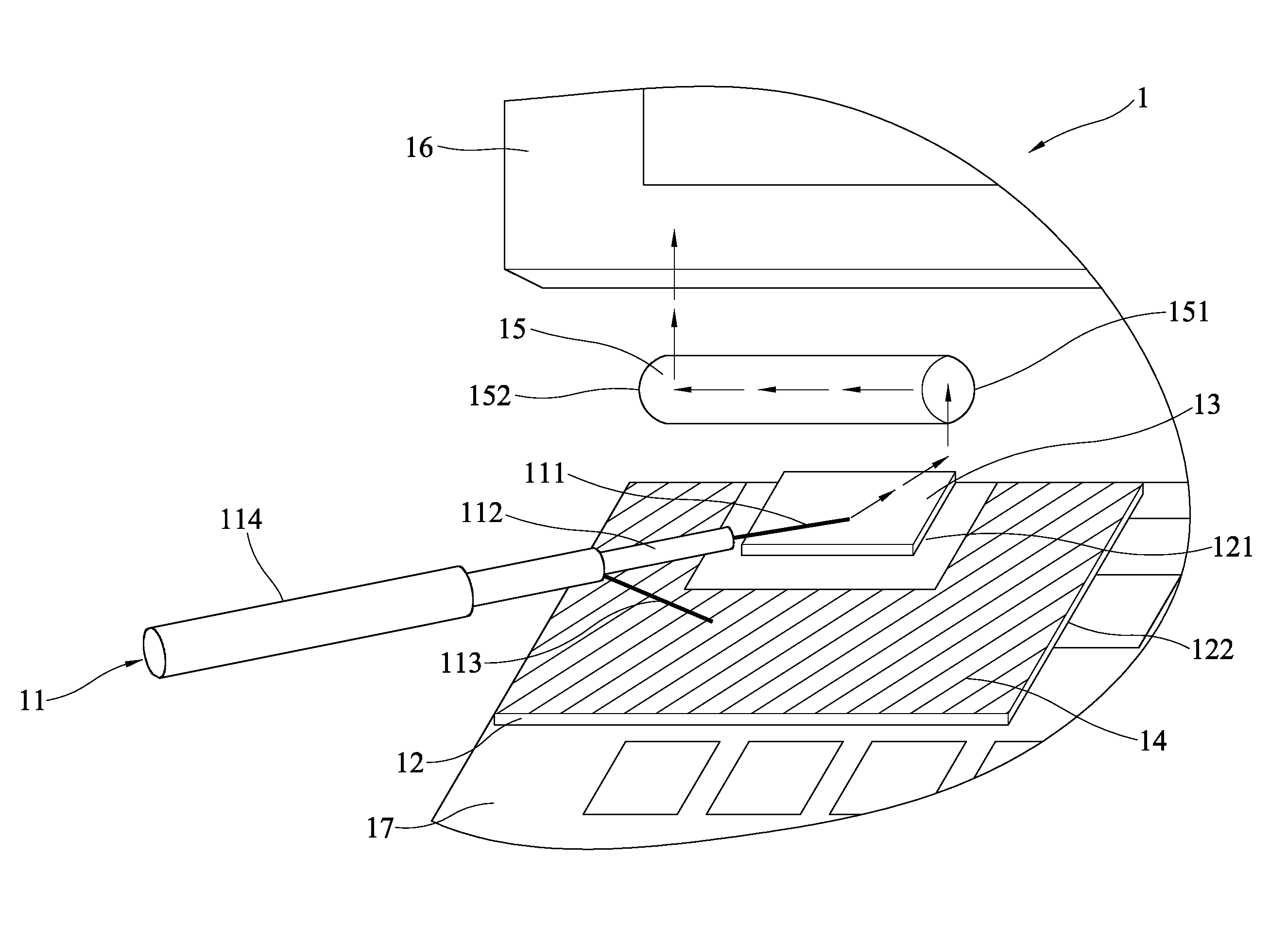
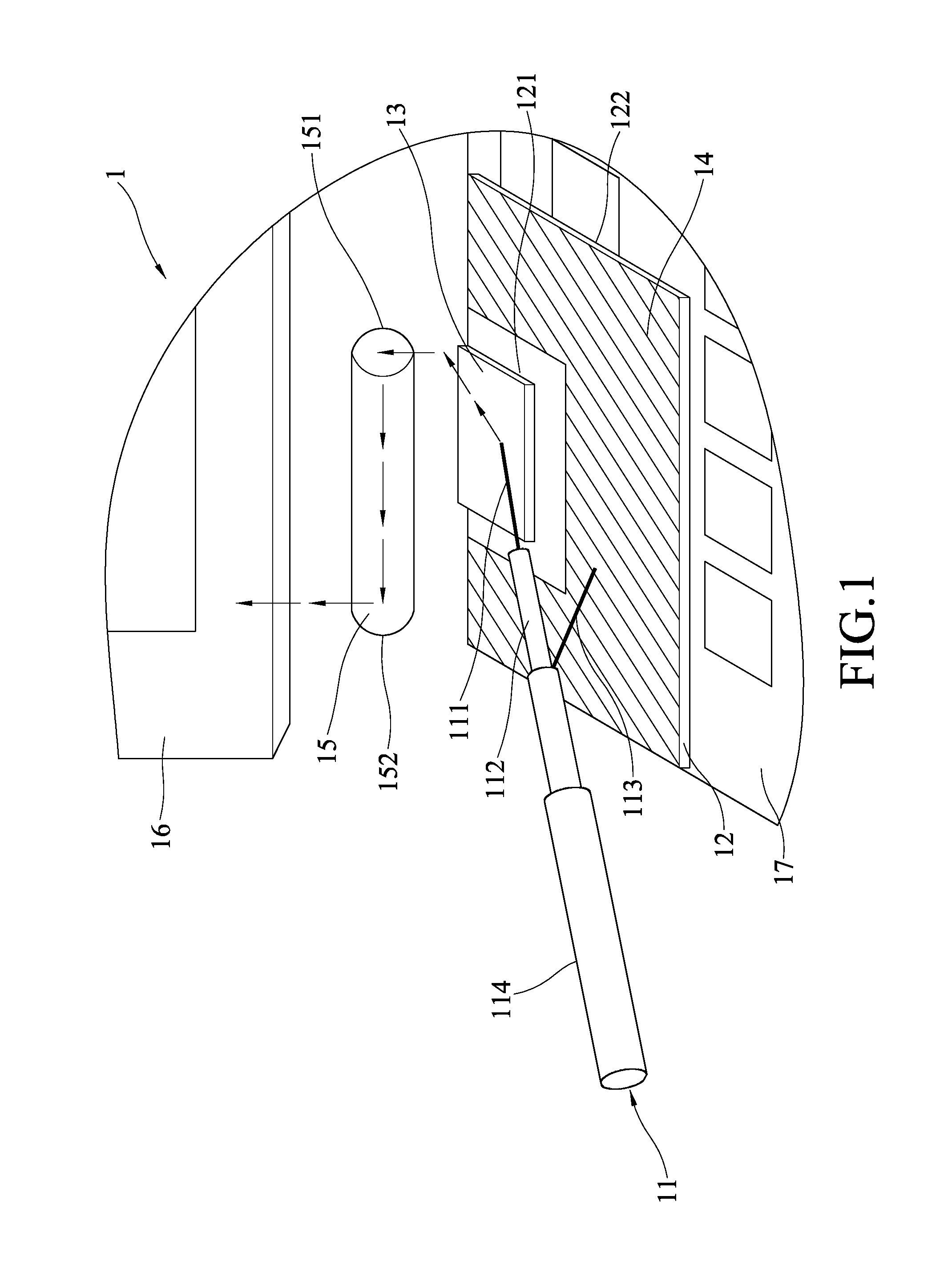
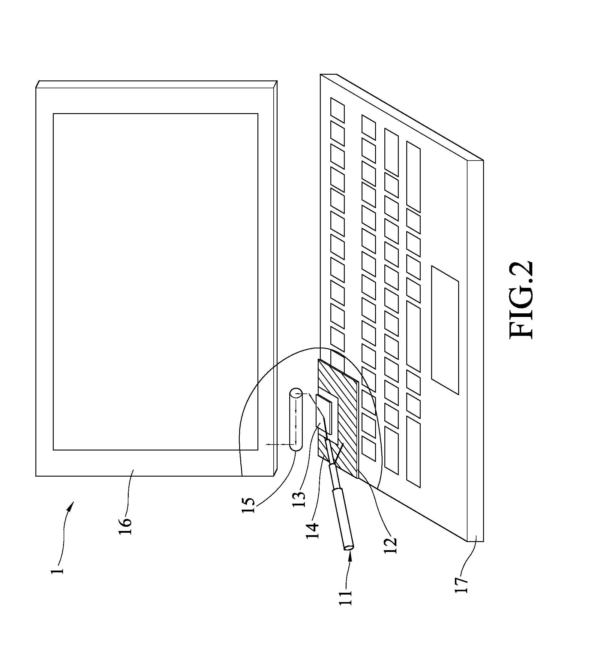
[0018]Refer to FIG. 1 a partially-enlarged perspective view schematically showing that a tuning circuit for a pivotal antenna is applied to a portable computer according to a first embodiment of the present invention. In this embodiment, the tuning circuit for a pivotal antenna comprises a feeder transmission cable 11, a microwave medium 12, an impedance-matching tuning circuit 13, a grounding plane 14, a pivotal shaft 15, a radiation conductor 16, and a carrier member 17.

[0019]The feeder transmission cable 11 is a high-frequency coaxial feeder cable and has a central wire 111, an insulating layer 112, an outer conductor 113 and a coating layer 114 from center to surface. The microwave medium 12 has a first plane 121 and a second plane 122 electrically isolated from the first plane 121. The impedance-matching tuning circuit 13 is arranged on the first plane 121 of the microwave medium 12 and connected with the central wire 111. The impedance-matching tuning circuit 13 is used to mod...


PUM


Abstract

A tuning circuit for a pivotal antenna comprises a feeder transmission cable, a microwave medium, an impedance-matching tuning circuit, a grounding plane, a pivotal shaft, a radiation conductor, and a carrier member. The feeder transmission cable has a central wire and an outer conductor. The microwave medium has a first plane and a second plane. The impedance-matching tuning circuit is arranged on the first plane and connected with the central wire. The grounding plane is arranged on the second plane and connected with the outer conductor. The pivotal shaft has a first end connected with the impedance-matching tuning circuit and a second end connected with the radiation conductor. The carrier member accommodates the microwave medium thereinside. The tuning circuit for a pivotal antenna of the present invention can provide superior impedance and bandwidth for a radiation conductor of an antenna.

Description

BACKGROUND OF THE INVENTION[0001]1. Field of the Invention[0002]The present invention relates to a tuning circuit for a pivotal antenna, particularly to a tuning circuit whose chip is integrated with a wireless transmission device having a pivotal shaft.[0003]2. Description of the Related Art[0004]Wireless communication products play import roles in modern daily life, such as portable computers, mobile phones, vehicle satellite navigation devices. They are wirelessly linked to another device via antennae that transceive electromagnetic wave in space.[0005]Antenna gain is a factor crucial to the performance of an antenna. How to layout an antenna inside an electronic device is a critical problem to upgrade the electromagnetic transmission efficiency of the antenna. Many wireless transmission devices belong to a pivotal-type design, wherein the radiation conductor is disposed in the border of the frame. However, the elbow region of the pivotal device may cause noise or interruption of...

Claims


Application Information

Patent Timeline
Patent Type & Authority Applications(United States)
IPC IPC(8): H03H7/38
CPCH01Q1/2266H01Q1/084
Inventor CHIU, TSUNG-WENHSIAO, FU-REN
Owner ADVANCED CONNECTEK INC
Why Eureka
Try Eureka