Super q dual mode cavity filter assembly

a cavity filter and super q technology, applied in the field of dual-mode microwave resonator filter, can solve the problems of increasing inter-channel distortion, increasing insertion loss, and reducing efficiency

Active Publication Date: 2012-03-22
HONEYWELL LIMITED HONEYWELL LIMITÉE
View PDF2 Cites 6 Cited by
  • Summary
  • Abstract
  • Description
  • Claims
  • Application Information

AI Technical Summary

Problems solved by technology

In contrast, filters having lower Q factors tend to exhibit increased insertion loss and a more gradual transitional band roll-off, wh...

Method used


Image

  • Super q dual mode cavity filter assembly
  • Super q dual mode cavity filter assembly
  • Super q dual mode cavity filter assembly

Examples


Embodiment Construction

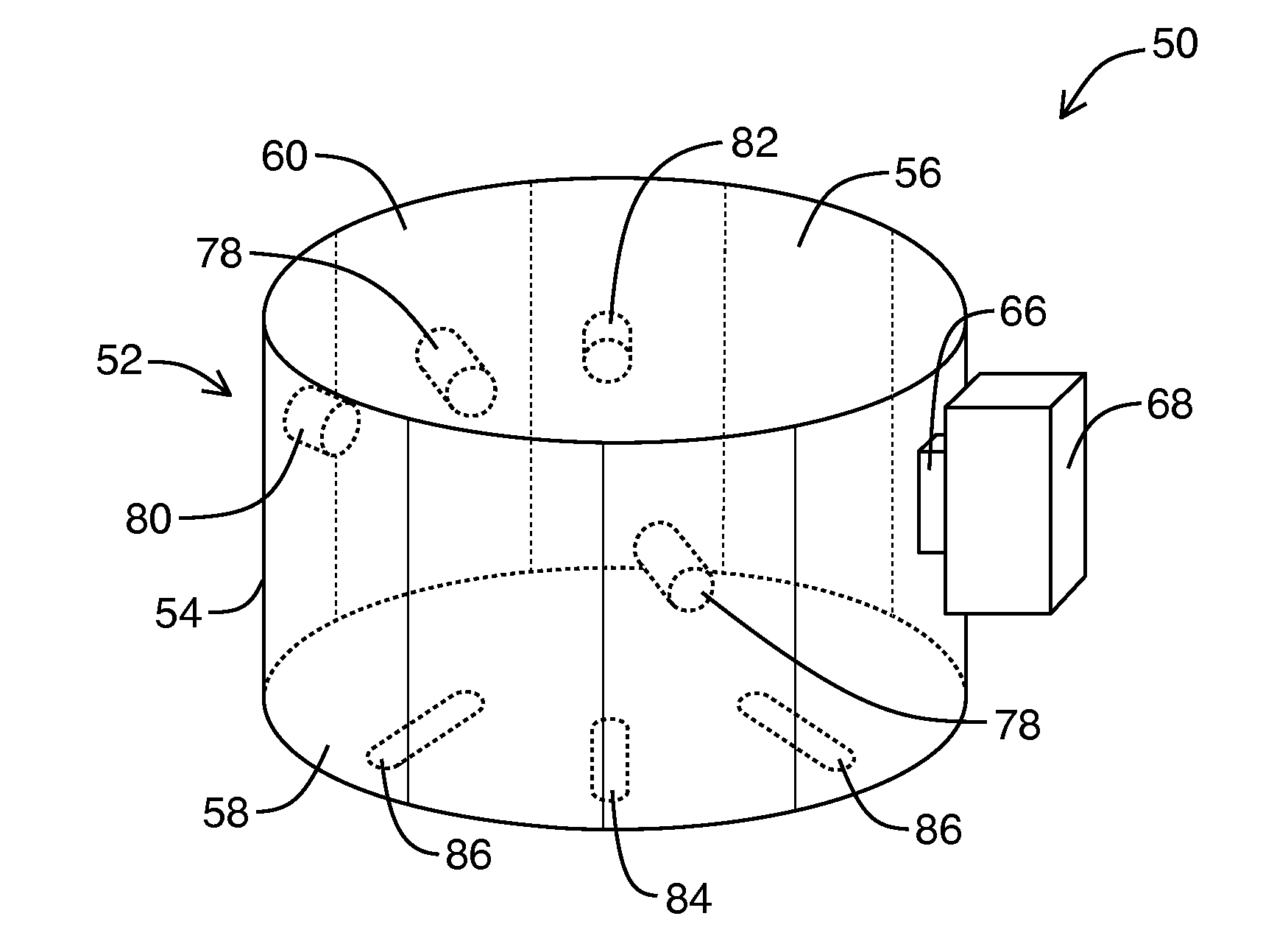
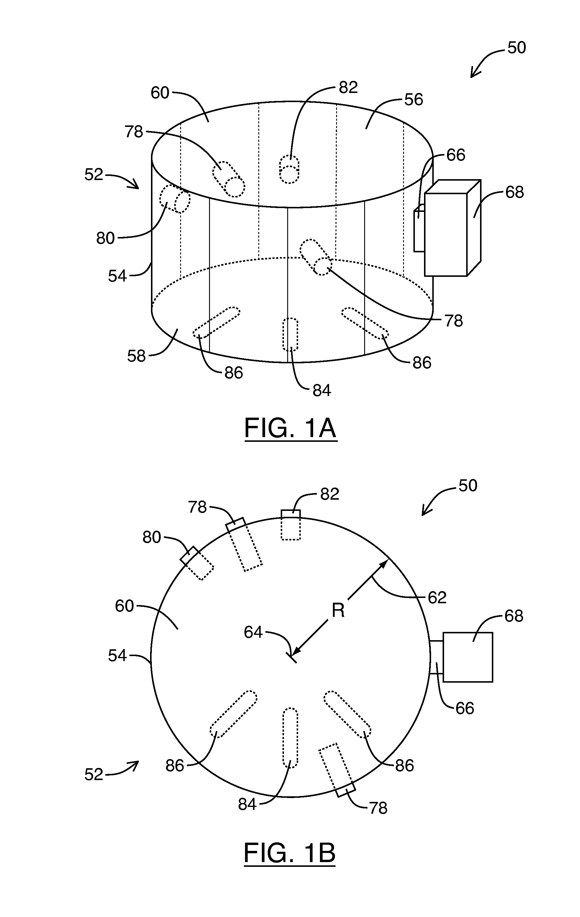
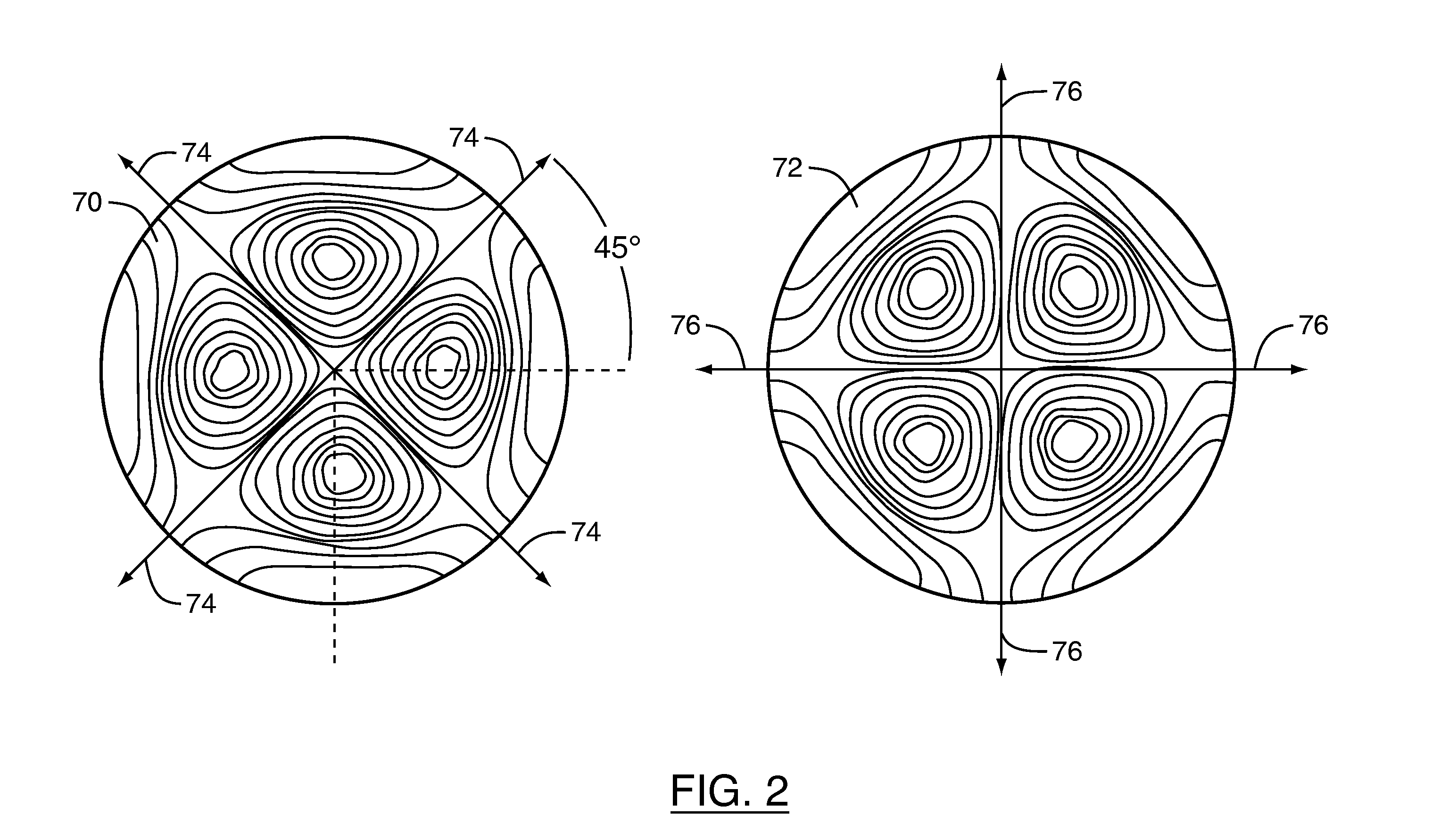
[0026]Microwave resonator filters are commonly designed to operate in the TE11N or TE011 mode for high Q factor applications because, at lower frequency ranges, such as the C band (4-8 GHz) or the Ku band (12-18 GHz), the TE11N or TE011 modes can offer better performance than other resonance modes. For example, low loss filters having Q factors up to about 16,000 are realizable using the TE11N or TE011 modes. Quality factors up to and exceeding those realizable using the TE11N or TE011 modes of the same or higher order can be also achieved by designing the microwave filter to operate in higher order resonance modes, such as the TE22N mode. However, for microwave filters designed for the C or Ku bands, the realized TE22N mode filter tends to be larger and bulkier as compared to the TE11N or TE011 modes. In certain telecommunications applications, such as satellite or spacecraft installations, where size and weight can be important design constraints, the additional weight and bulk in...


PUM


Abstract

A microwave cavity filter is configured for operation in the dual TE22N mode to realize a very high Q factor at very high frequency ranges. The microwave filter is formed from using one or more cylindrical cavities in which two orthogonal field polarizations of the TE22N mode are excited and coupled together by means of a coupling element. Different combinations of inter-cavity irises provide for both direct and cross-coupling of aligned field polarizations in adjacent cavities, as required, to realize complex filter functions. The irises may be formed in either a side or end wall of the cavities for both collinear and planar mount configuration. Negative mode coupling also allows for transmission zeros to be realized on either side of the filter passband.

Description

FIELD[0001]Embodiments described herein relate generally to microwave resonator filters and, more particularly, to dual mode microwave resonator filters exhibiting low loss at very high frequency ranges.INTRODUCTION[0002]A microwave filter is an electromagnetic device that can be tuned to pass energy within bands of frequencies encompassing resonant frequencies of the filter, while substantially suppressing inter-band frequencies. The resulting bandpass characteristic of the microwave filter can be described by one or more different performance criteria. For example, insertion loss describes the amount of signal loss exhibited in the microwave filter's passband, rejection (or “isolation”) describes the amount of signal attenuation exhibited in the filter's stopband, return loss relates to the ratio of signal power incident on and reflected from the filter, loss variation (sometimes referred to as “ripple”) describes the flatness of the passband, and group delay is related to the pha...

Claims


Application Information

Patent Timeline
IPC IPC(8): H01P1/20H01P7/06
CPCH01P7/06H01P1/2082
Inventor YASSINI, BAHRAMYU, MING
Owner HONEYWELL LIMITED HONEYWELL LIMITÉE
Why Eureka
Try Eureka