
Method of dynamic cell tracking in a sample

a cell tracking and sample technology, applied in image analysis, instruments, computing, etc., can solve the problems of increasing the amount of data, the analysis of this data has not kept pace, and the amount of data has increased, so as to improve the cell tracking accuracy

Active Publication Date: 2012-03-22
GLOBAL LIFE SCI SOLUTIONS USA LLC
View PDF2 Cites 8 Cited by
  • Summary
  • Abstract
  • Description
  • Claims
  • Application Information

AI Technical Summary

Benefits of technology

[0013]One advantage with the method and system according to the present invention is that it provides an automated decision making system for validating the events generated by particle filter which may improve the cell tracking accuracy over existing cell tracking algorithms by up to 30%.

Problems solved by technology

In the past decade, there has been an explosive increase in the amount of data measurements conducted relating to biological processes.
However, the amount of data has increased, but the analysis of this data has failed to keep pace.
The costs of tracking are prohibitively high for high throughput screening.
This process of tracking the marked cell movement is error-prone and time consuming, because even though the one cell was marked it still may not be distinguishable from the plurality of cells existing from one frame to another.
Also, the dye utilized to mark the cell may hinder the normal cell functions so one would not obtain a true image of how the cell works as it moves from one frame to another.
However, for cellular images sequences, there are many interfering factors, e.g. background clutter and it is difficult to produce a clean image for cellular boundaries, which often causes the collapse of Kalman filter tracking.
However there is a penalty to be paid in loss of speed.
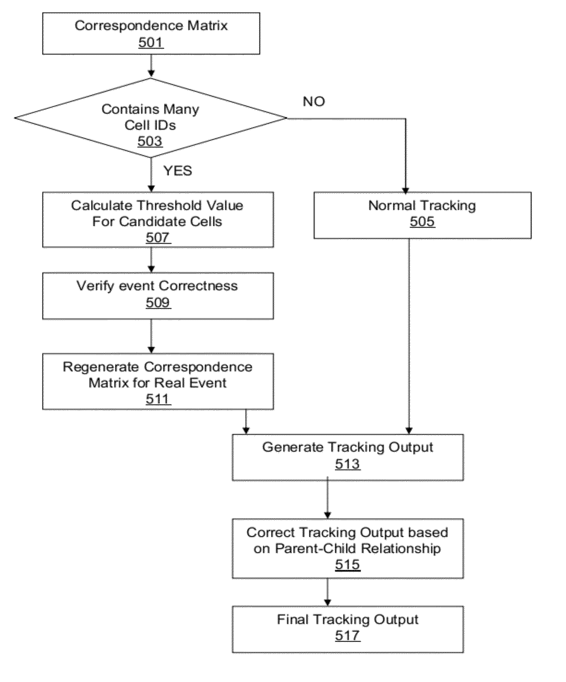
However, sometimes the cell correspondence leads to generate a false event and is required to verify the cell correspondence.

Method used


Image

  • Method of dynamic cell tracking in a sample
  • Method of dynamic cell tracking in a sample
  • Method of dynamic cell tracking in a sample

Examples


examples demonstrating

Particle Filter Performance

[0099]FIGS. 6a and 6b shows one example wherein the introduced improvement of the particle algorithm by verification of events has been implemented. FIG. 6a shows the previous frame and FIG. 6b the current. When the images 6a and 6b were evaluated by particle filtering, the tracking output for cell ID 12 was Cloud_to_Measure [12]=13, 14, whereby this event is captured as a cell division event. However after verification of the correctness of the cell division event, the event is corrected to represent migration of one new cell, and unchanged events for the two cells in the previous frame, ie. Cloud_to_Measure [12]=13 and Measure_to_Cloud [14]=NULL.

[0100]FIGS. 7a and 7b shows another example wherein evaluation by particle filtering captures this as a cell division event with a one-to-many relationship i.e. Cloud_to_Measure [12]=13, 14, Measure_to_Cloud [13]=12 and Measure_to_Cloud [14]=12. In this case, the verification of the correctness of the cell divisi...


PUM


Abstract

This invention provides a method of dynamic cell tracking in a sample comprising the steps of, generating a correspondence measure between cells in two consecutive time-elapsed images of a sample, evaluating said correspondence measure to generate events linking individual cells in the two images, the events being selected from the group: unchanged, cell removal, cell migration, cell collision and cell division, and providing a tracking output of events linking individual cells in the two images. In the invention, the step of establishing linking events involves verifying the correctness of generated cell collision and cell division events, by calculating an adaptive threshold value for each such event and comparing the threshold value with an event parameter. There is further provided a system for dynamic cell tracking in a sample.

Description

CROSS-REFERENCE TO RELATED APPLICATIONS[0001]This application is a filing under 35 U.S.C. §371 and claims priority to international patent application number PCT / SE2010 / 050530 filed May 17, 2010, published on Nov. 25, 2010 as WO 2010 / 134875, which claims priority to application number 1023 / DEL / 2009 filed in India on May 19, 2009.FIELD OF THE INVENTION[0002]The present invention relates to a system and method for determining the location of biological material.BACKGROUND OF THE INVENTION[0003]In the past decade, there has been an explosive increase in the amount of data measurements conducted relating to biological processes. This explosion can be attributed mainly to improvements in technology-particularly, computer technology. However, the amount of data has increased, but the analysis of this data has failed to keep pace. Accordingly, there is an increasing need for automated analysis of data.[0004]One of the most fundamental observations of biological data is to measure the behav...

Claims


Application Information

Patent Timeline
IPC IPC(8): G06K9/00G06V10/62G06V20/69
CPCG06K9/00127G06T7/208G06K2009/3291G06T7/277G06V20/69G06V10/62
Inventor MAHATO, BIKASH CHANDRA
Owner GLOBAL LIFE SCI SOLUTIONS USA LLC
Learn More