Suction button assembly for endoscope

a technology of endoscope and suction button, which is applied in the field of suction button assembly for endoscope, can solve the problems of serious failure of the plunger and large friction resistance, and achieve the effect of small resistance between the plunger and the cylinder housing

Inactive Publication Date: 2012-03-22
FUJIFILM CORP
View PDF2 Cites 7 Cited by
  • Summary
  • Abstract
  • Description
  • Claims
  • Application Information

AI Technical Summary

Benefits of technology

[0034]Therefore, resistance between a plunger and a cylinder housing can be small, becau

Problems solved by technology

Resistance of the friction may be so large that failure of the plunger will occur seriously, for example the plunger will

Method used


Image

  • Suction button assembly for endoscope
  • Suction button assembly for endoscope
  • Suction button assembly for endoscope

Examples


Embodiment Construction

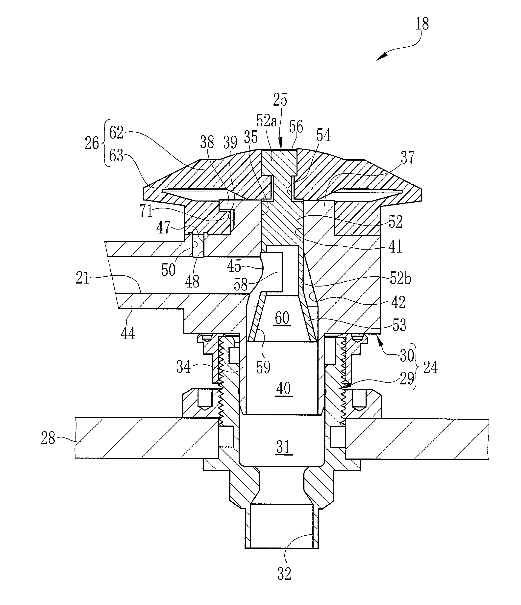
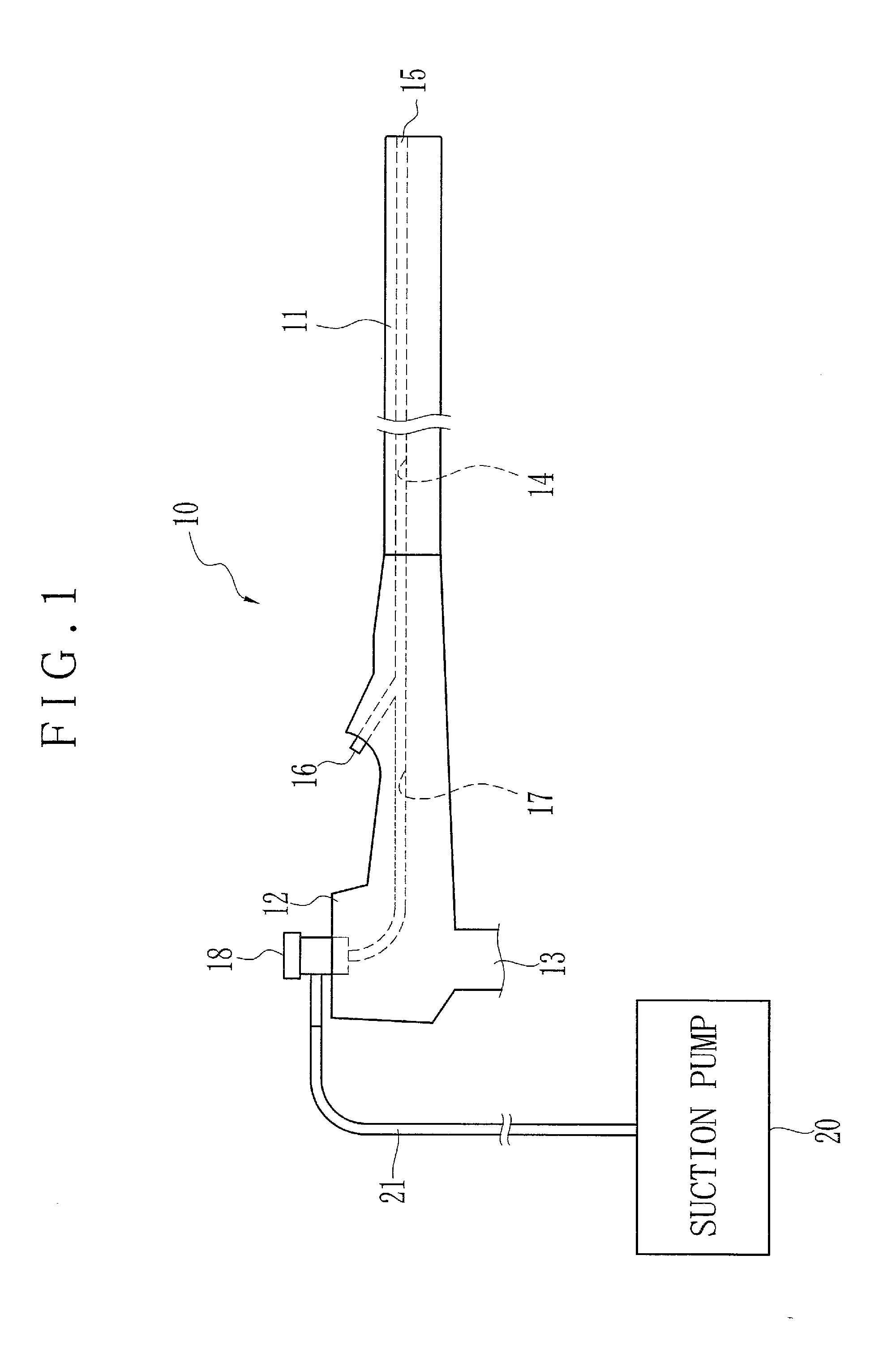
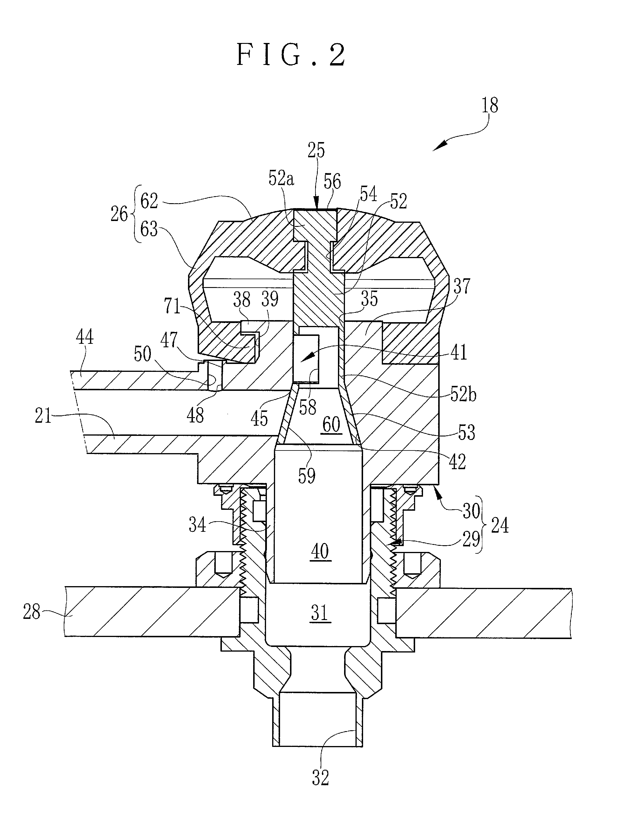
[0050]In FIG. 1, an endoscope 10 is a bronchoscope, and includes an elongated tube 11 or guide tube, an operation unit 12 and a universal cable 13. The elongated tube 11 is entered in a bronchus as a body cavity. The operation unit 12 is disposed at a proximal end of the elongated tube 11. An endoscope system for use includes a processing apparatus (not shown) and a light source apparatus (not shown). The universal cable 13 is connected to those apparatuses.

[0051]An instrument channel 14 is formed in the elongated tube 11 for entry of a forceps or other instrument for treatment. A distal instrument opening 15 is disposed at a distal end of the instrument channel 14, and open in a distal surface of the elongated tube 11. A proximal instrument opening 16 is disposed at a proximal end of the instrument channel 14, and open in the operation unit 12. A seal cap (not shown) is fitted in the proximal instrument opening 16 for closing at a normal time before entry of the instrument. Note th...


PUM


Abstract

A suction button assembly of a valve structure for an endoscope includes a cylinder housing, cylinder passage, plunger or piston unit, cylinder opening, plunger stem, flow opening, valve sleeve and flow channel. A valve opening is formed in a side surface of the valve sleeve at an end of the flow channel, closed by a wall of the cylinder passage when the plunger is in the closed position, for shut-off between the suction channel and the discharge conduit, and registered with the flow opening when the plunger is in the open position, for communication between the suction channel and the discharge conduit. A valve engaging surface is formed partially with the cylinder passage, has the flow opening, and has an inner diameter decreasing in an upward direction. The valve sleeve is tapered and tightly contacted on the valve engaging surface when the plunger is in the closed position.

Description

BACKGROUND OF THE INVENTION[0001]1. Field of the Invention[0002]The present invention relates to a suction button assembly for an endoscope. More particularly, the present invention relates to a suction button assembly for an endoscope, in which resistance between a plunger and a cylinder housing can be small, and suction of fluid from a body cavity can be controlled precisely.[0003]2. Description Related to the Prior Art[0004]An endoscope includes an operation unit and an elongated tube extending distally from the operation unit. The elongated tube includes a suction channel and a distal opening. The suction channel extends in an axial direction. The distal opening is formed in a distal end face of the elongated tube, as a distal end of the suction channel. A suction button assembly is incorporated in the operation unit. A specific example of the suction channel is an instrument channel, which is used for penetration of a forceps or other medical instrument and for supply of washin...

Claims


Application Information

Patent Timeline
IPC IPC(8): A61M1/00
CPCA61B1/00068A61B1/00128A61B1/015A61M2039/226A61M1/7411
Inventor YAMANE, KENJI
Owner FUJIFILM CORP
Why Eureka
Try Eureka