Unlock instant, AI-driven research and patent intelligence for your innovation.

Data transmission device, data recepton device, and transmission method

a data transmission device and data reception technology, applied in the direction of instruments, coding, code conversion, etc., can solve the problems of enormous data volume of mobile devices such as portable telephone devices, and achieve the reduction of the number of data transitions on respective signal lines between the data transmission device and the data reception device, and the effect of reducing power consumption

Active Publication Date: 2012-03-22
PANASONIC INTELLECTUAL PROPERTY MANAGEMENT CO LTD
View PDF5 Cites 3 Cited by
  • Summary
  • Abstract
  • Description
  • Claims
  • Application Information

AI Technical Summary

Benefits of technology

[0017]The data transmission device according to the present invention generates encoded data by performing encoding in such a manner that an n-bit code is associated with the difference data between data for n bits of transmission data and previous data for n bits. The number of bit inversions in the n-bit codes with respect to the n-bit codes associated with the difference data “0” becomes smaller as the absolute value of the difference data becomes smaller. By transmitting the encoded data through the n-bit signal lines, the number of data transitions on respective signal lines between the data transmission device and the data reception device is reduced. In this manner, a lower power consumption and

Problems solved by technology

In recent years, the amount of data handled by mobile devices such as portable telephone devices has become enormous.

Method used


Image

  • Data transmission device, data recepton device, and transmission method
  • Data transmission device, data recepton device, and transmission method
  • Data transmission device, data recepton device, and transmission method

Examples


first embodiment

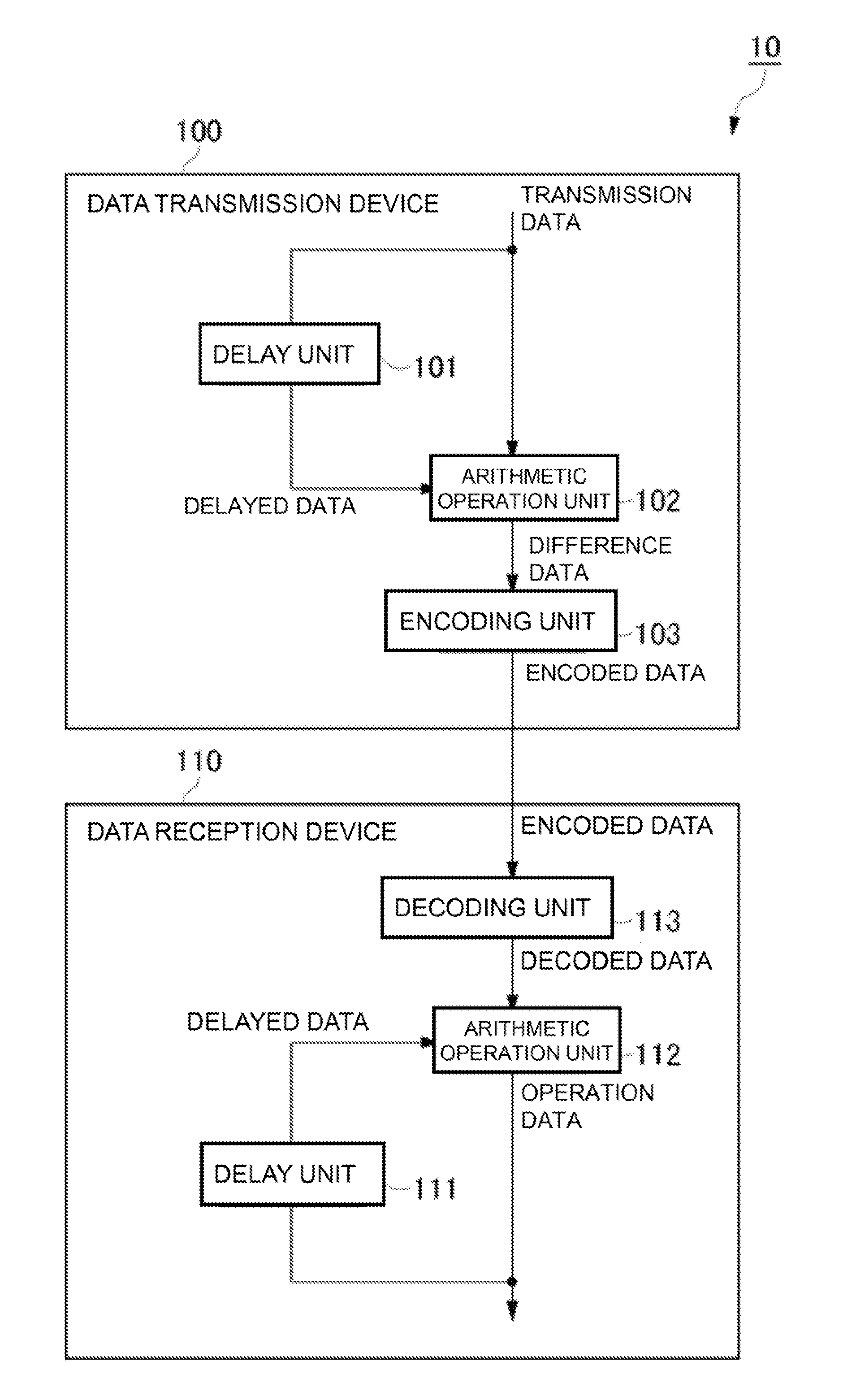
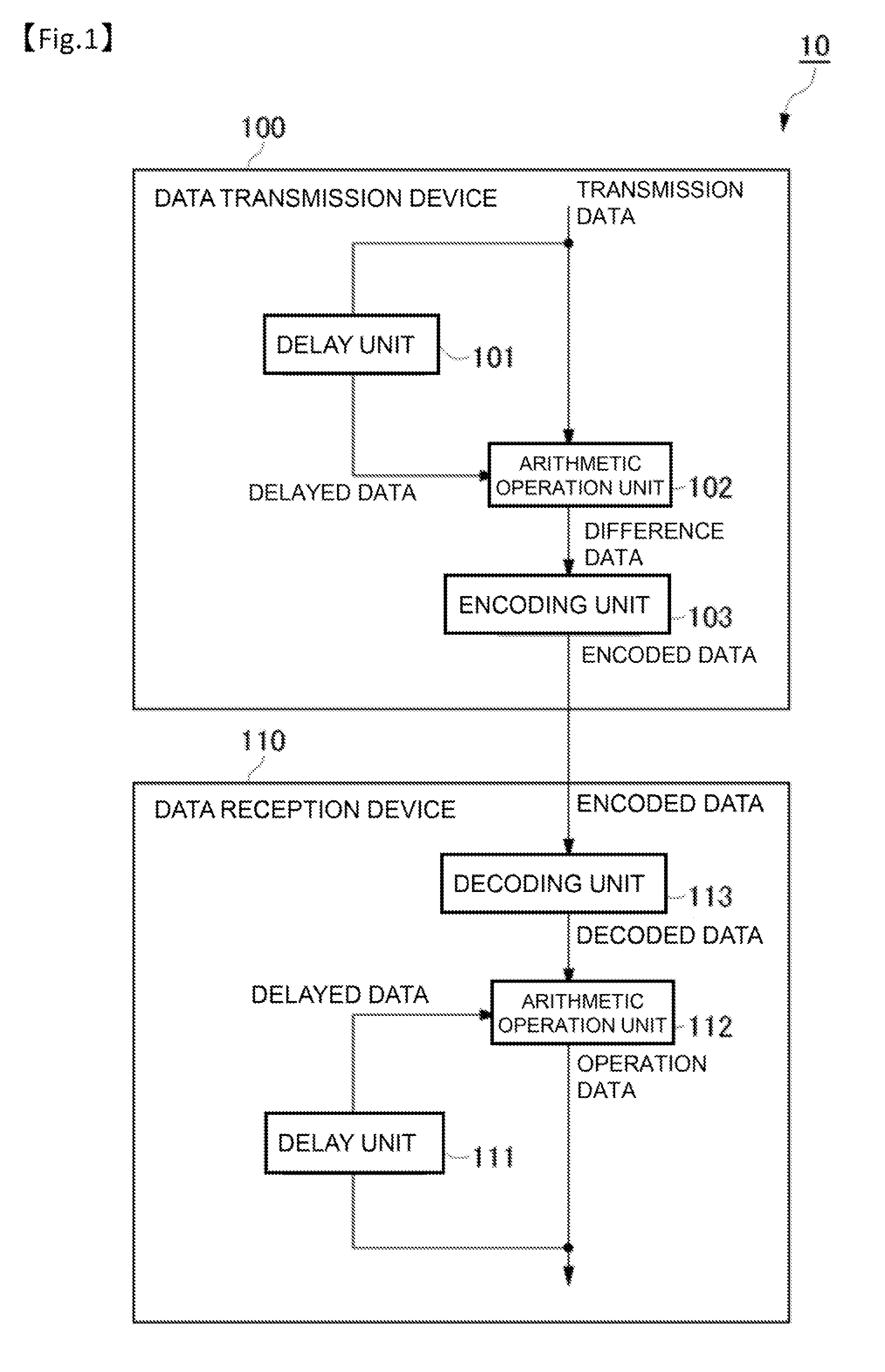
[0028]FIG. 1 is a block diagram of a data transmission system according to a first embodiment of the present invention. The data transmission system 10 includes a data transmission device 100 that transmits data, and a data reception device 110 that receives data. In this embodiment, transmission data is image data in an RGB format, the data transmission device 100 is a system LSI, and the data reception device 110 is a display device. Those components form a display data transmission system.

[0029]In the data transmission system 10, 8-bit data about the respective elements of RGB (24 bits in total) is transmitted in parallel between the data transmission device 100 and the data reception device 110 through 24-bit signal lines.

[0030]The data transmission device 100 includes a delay unit 101, an arithmetic operation unit 102, and an encoding unit 103. Image data that is transmission data is input to the data transmission device 100 in pixel sequential order. One frame of image data is...

second embodiment

[0056]FIG. 4 is a block diagram of a data transmission system according to a second embodiment of the present invention. The data transmission system 20 includes a data transmission device 200 that transmits data, and a data reception device 210 that receives data.

[0057]In this embodiment, the data transmission device 200 is a system LSI, and the data reception device 210 is a display device, as in the first embodiment. The data transmission system 20 is a display data transmission system formed by those devices, and transmission data is image data in an RGB format, as in the first embodiment.

[0058]In the data transmission system 20 of this embodiment, 8-bit data about each of the elements of RGB (24 bits in total) is transmitted in parallel between the data transmission device 200 and the data reception device 210 through 24-bit signal lines, as in the data transmission system 10 of the first embodiment.

[0059]The data transmission device 200 includes a first delay unit 201, a first...

third embodiment

[0074]FIG. 6 is a block diagram of a data transmission system according to a third embodiment. The data transmission system 30 is a system formed by connecting a data write device 300 and a data read device 310 that are system LSIs to a storage device 320 as a memory device by memory buses.

[0075]Write data and read data are image data in an RGB format. The data write device 300 includes a delay unit 301, an arithmetic operation unit 302, and an encoding unit 303. The data read device 310 includes a delay unit 311, an arithmetic operation unit 312, and a decoding unit 313.

[0076]The data write device 30C and the storage device 320 are connected by an 8-bit memory bus for the data about each of the elements of RGB (24 bits in total) and the storage device 320 and the data read device 310 are also connected by an 8-bit memory bus for the data about each of the elements of RGB (24 bits in total).

[0077]The operations of the delay unit 301, the arithmetic operation unit 302, and the encodi...


PUM


Abstract

The present invention provides a data transmission system that reduces the number of data transitions on signal lines in data transmission via parallel buses between devices such as memory interfaces and liquid crystal interfaces, and can realize a lower power consumption and lower EMI noise. A data transmission device (100) transmits transmission data converted into encoded data, using n-bit (n being k×m, k and m being natural numbers each equal to or greater than 1) signal lines. The data transmission device (100) includes: an arithmetic operation unit (102) that generates difference data that represents the difference between first data for m bits of the transmission data and second data for m bits of the previous transmission data; and an encoding unit (103) that encodes the difference data and generates m-bit encoded data. The encoding unit (103) performs encoding to associate the encoded data with the difference data in such a manner that the number of bit inversions with respect to the encoded-data associated with difference data “0” becomes smaller as the absolute value of the difference data becomes smaller.

Description

CROSS-REFERENCE TO RELATED APPLICATION[0001]This application claims benefit of priority to Japanese Patent Application No. 2009-140307, filed on Jun. 11, 2009, the contents of which are incorporated hereinto by reference.TECHNICAL FIELD[0002]The present invention relates to data transmission devices, data reception devices, and data transmission methods for performing data transmission through parallel buses.BACKGROUND ART[0003]In recent years, the amount of data handled by mobile devices such as portable telephone devices has become enormous. Therefore, like large-sized apparatuses, mobile devices need to reduce power consumptions and EMI (Electro-Magnetic Interference) noise in data transfers between devices such as memory interfaces and liquid crystal display interfaces.[0004]In view of this, there have been techniques for lowering power consumptions and EMI noise by reducing the number of data transitions (hereinafter also referred to as the “number of bit inversions”) on the si...

Claims


Application Information

Patent Timeline
IPC IPC(8): G06F11/00
CPCG09G3/20H04L25/4915G09G2370/08
Inventor ISHIOKA, TOSHIYUKI
Owner PANASONIC INTELLECTUAL PROPERTY MANAGEMENT CO LTD