Fuel tank structure

a fuel tank and structure technology, applied in the direction of liquid handling, caps, applications, etc., can solve the problems of fuel not being bled, complicated structure, and man-hours of work, and achieve the effect of simple structure and convenient work

Inactive Publication Date: 2012-03-29
HONDA MOTOR CO LTD
View PDF8 Cites 16 Cited by
  • Summary
  • Abstract
  • Description
  • Claims
  • Application Information

AI Technical Summary

Benefits of technology

[0006]The present invention is directed toward a fuel tank structure allowing bleeding of the fuel through the fuel filler port with a simple structure that facilitates the work.

Problems solved by technology

However, when a flame arrester is provided in a fuel filler port of a fuel tank as described in JP-A No. 2009-101855, even if the fuel is to be bled using a fuel bleeding pipe as described in JP-A No. 2005-47334, the flame arrester becomes an obstacle, so that the fuel bleeding pipe cannot be inserted to the bottom of the fuel tank, and therefore the fuel cannot be bled.
Also, in order to allow the fuel bleeding pipe to reach the bottom of the fuel tank, it may be possible to arrange an opening through which the fuel bleeding pipe is inserted in the flame arrester; however, in this case, in order to secure the function of the flame arrester, the opening is required to be blocked after the fuel has been bled, which presents problems that the structure becomes complicated and the work requires man-hours.

Method used


Image

  • Fuel tank structure
  • Fuel tank structure
  • Fuel tank structure

Examples


first embodiment

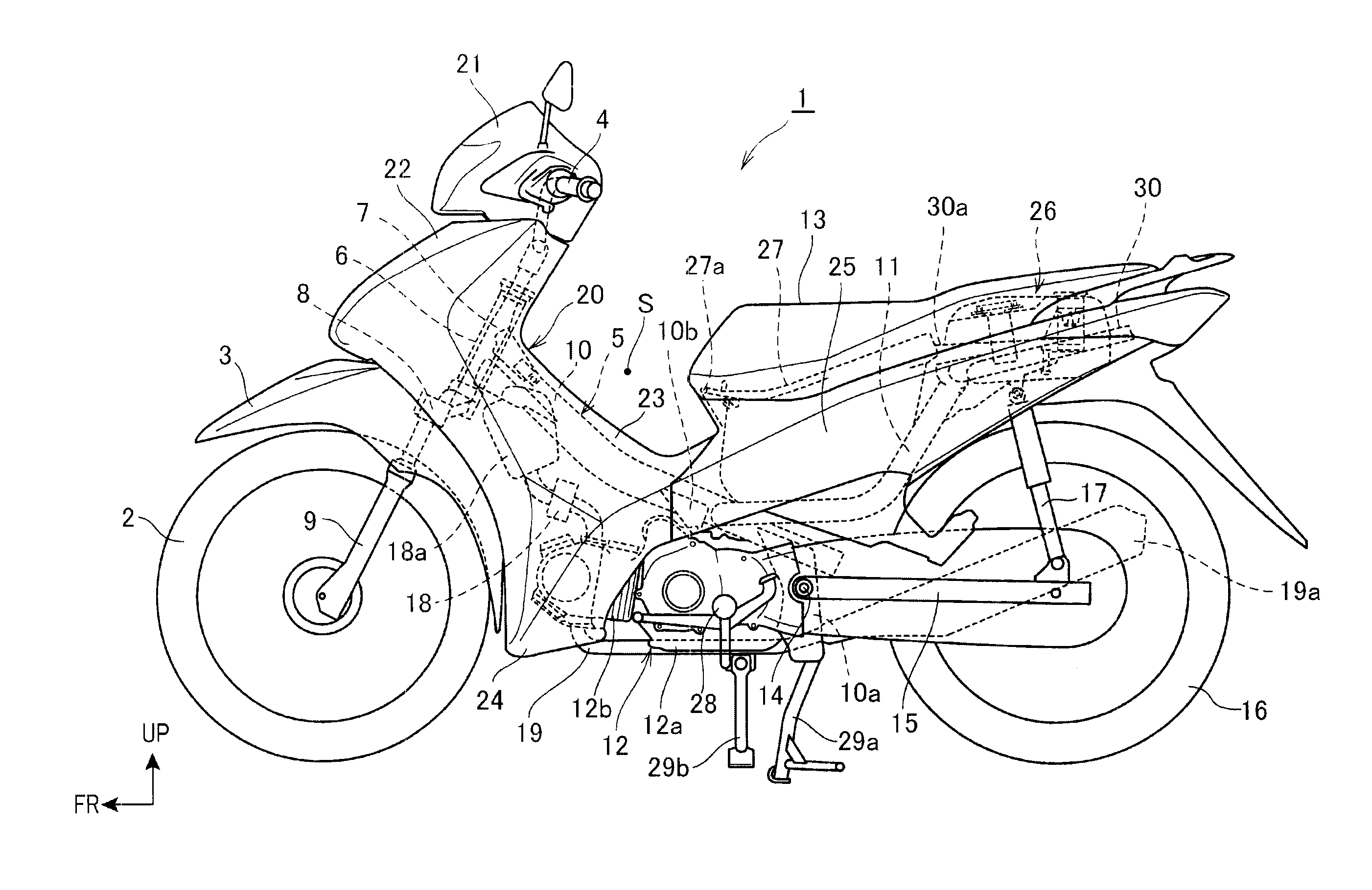
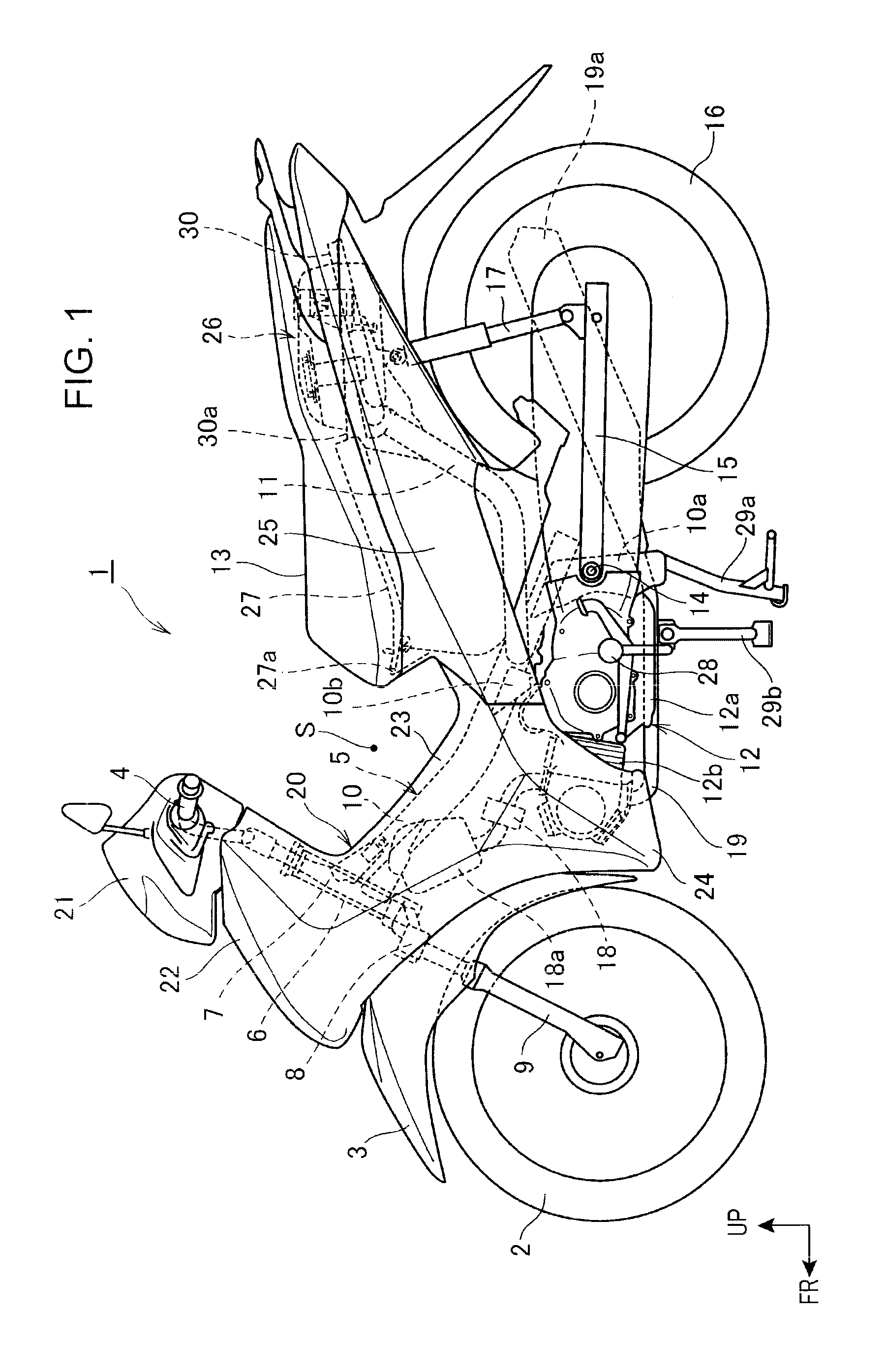
[0039]FIG. 1 is a left side view of a motorcycle to which is applied a fuel tank structure according to the present invention.

[0040]A front wheel 2 is rotatably arranged in the front part of a motorcycle 1 (saddle-ride type vehicle), and a front fender 3 is arranged above the front wheel 2. A bar handle 4 for steering the front wheel 2 is arranged above the front fender 3. A steering stem 7 is rotatably supported by a head pipe 6 formed at the front end of a vehicle body frame 5, and the bar handle 4 is arranged on the top of the steering stem 7.

[0041]A sheet-like lower bridge 8 extending to the right and left is arranged at the bottom of the steering stem 7, the upper ends of right and left front forks 9 are fixed to the right and left ends of the lower bridge 8, and the front wheel 2 is rotatably supported by the bottom parts of the front forks 9.

[0042]The vehicle body frame 5 includes a main frame 10 constructed of one steel pipe material with a rectangular cross section extendin...

second embodiment

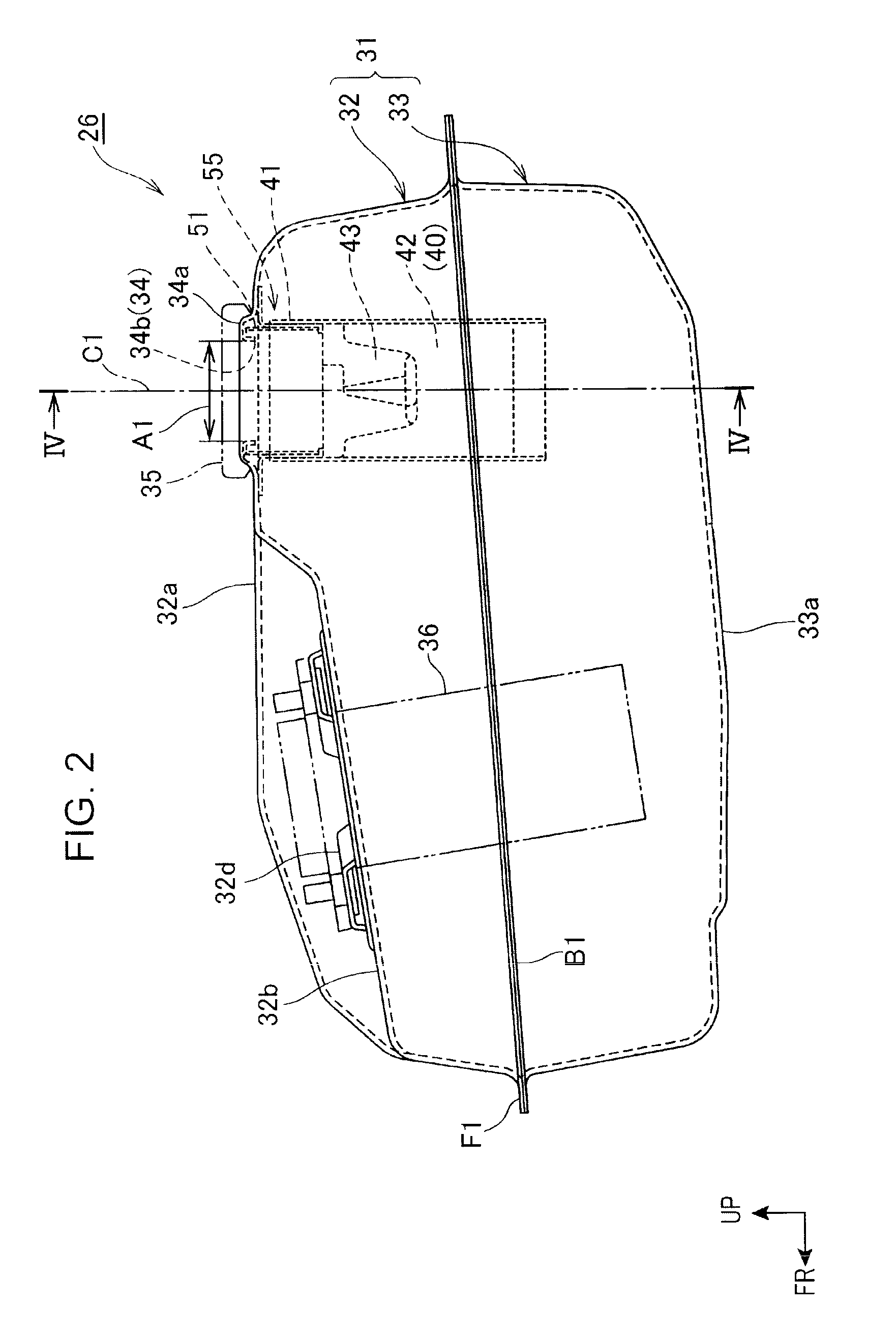
[0103]FIG. 7 is a cross-sectional view of the fuel filler port device 40 in the

[0104]As shown in FIG. 7, the fuel feed guiding cylinder 41 includes the flange part 41b and a cylindrical peripheral wall part 141a (side face part) continuing to the flange part 41b. In the peripheral wall part 141a, the guide cylinder opening 61 is formed.

[0105]The gun stopper body 43 is welded to the inner peripheral surface of the upper part 42c in a state the top edges of the joining sheet parts 43a abut on the lower end of the peripheral wall part 141a. The inner peripheral surface of the joining sheet parts 43a and the inner peripheral surface of the peripheral wall part 141a continue to each other and constitute an inner peripheral surface 141d to which the outer peripheral surface 51a of the cylindrical ring 51 is fitted.

[0106]In the cylindrical ring 51, the ring upper end 51b abuts on the inner surface of the frame part 34a and the ring lower end 51c abuts on the upper surface of the step part ...

third embodiment

[0109]FIG. 8 is a left side view of a motorcycle to which is applied a fuel tank structure of the

[0110]In a motorcycle 101 shown in FIG. 8, a vehicle body frame 102 thereof includes a head pipe 103 supporting a front wheel suspension system in a steerable manner, a main frame 104 extending rearward from the head pipe 103 and thereafter curvedly extending obliquely downward to the rear, a down tube 105 extending obliquely downward to the rear from the head pipe 103 and located below the main frame 104, right and left pivot plates 106 connected to the rear part of the main frame 104 and supporting rear swing arms 112 of a rear wheel suspension system in a vertically rockable manner, and a seat frame 115 extending rearward from the main frame 104.

[0111]Right and left front forks 108 are supported through the head pipe 103, and a front wheel 107 is supported by the lower ends of the front forks 108. A handlebar 109 for steering is arranged on the top of the front forks 108. An engine 11...


PUM

PropertyMeasurementUnit
cylindrical shapeaaaaaaaaaa
inner diameteraaaaaaaaaa
outer diameteraaaaaaaaaa

Abstract

A fuel tank structure including a fuel tank, a fuel filler port device formed in a cylindrical shape and arranged in the fuel tank, and a flame arrester arranged in the fuel filler port device and disposed inside the fuel tank. A fuel bleeding opening is formed in a peripheral wall part of the fuel filler port device and an arrester peripheral wall part. A cylindrical ring disposed so as to urge itself against the peripheral wall part and block the fuel bleeding opening.

Description

BACKGROUND OF THE INVENTION[0001]1. Field of the Invention[0002]The present invention generally relates to a fuel tank structure equipped with a flame arrester and, more particularly, to a fuel bleed opening and to a structure for closing the fuel bleed opening.[0003]2. Description of Related Art[0004]In a fuel tank of a motorcycle it is known to provide a wire-netting style flame arrester inside a fuel filler port of a fuel tank to prevent invasion of a fire source into the fuel tank while allowing the fuel to be fed through the fuel filler port. See, for example, JP-A No. 2009-101855. It is also known, in a fuel tank of a saddle-ride type vehicle, to insert a fuel bleeding pipe through a fuel filler port to bleed the fuel inside the fuel tank. In this regard see, for example, JP-A No. 2005-47334.[0005]However, when a flame arrester is provided in a fuel filler port of a fuel tank as described in JP-A No. 2009-101855, even if the fuel is to be bled using a fuel bleeding pipe as des...

Claims


Application Information

Patent Timeline
Patent Type & Authority Applications(United States)
IPC IPC(8): B65D41/00
CPCB60K15/04B62K2202/00B62J35/00B60W2300/365
Inventor HISADOMI, MASARUYAMADA, HIROSHI
Owner HONDA MOTOR CO LTD
Why Eureka
Try Eureka