Liquid-sealed antivibration device

a technology of anti-vibration and sealing seal, which is applied in the direction of shock absorbers, machine supports, mechanical apparatus, etc., can solve the problems of increasing cost, increasing cost, and pushed up cost, and achieves the suppression of excessive flexural deformation, low tensile strength, and secure durability

Active Publication Date: 2012-03-29
TOYO TIRE & RUBBER CO LTD +1
View PDF12 Cites 20 Cited by
  • Summary
  • Abstract
  • Description
  • Claims
  • Application Information

AI Technical Summary

Benefits of technology

[0016]According to the present invention, by forming the elastic membrane using butyl rubber or halogenated butyl rubber, an abnormal sound generated by the collision between the elastic membrane and a member made of a rigid material can be reduced.
[0017]According to the first mode of the present invention, an abnormal sound generated by the collision between the elastic membrane and the displacement restricting member can be reduced. Butyl rubber and halogenated butyl rubber possess low tensile strength in general and hence, it may be considered that the use of butyl rubber and halogenated butyl rubber is not suitable for forming a film-like elastic membrane which is assembled into the inside of a liquid chamber of a liquid-sealed antivibration device. However, according to the first mode of the present invention, the displacement of the elastic membrane is restricted by a pair of displacement restricting members so that the excessive flexural deformation can be suppressed and hence, it is possible to compensate for the above-mentioned defect of butyl rubber or halogenated butyl rubber whereby the elastic membrane can secure durability. Accordingly, the liquid-sealed antivibration device can reduce an abnormal sound generated by the collision of the elastic membrane while suppressing both the increase of cost and the lowering of performances.
[0018]According to the second mode of the present invention, in the same manner as the first mode, the liquid-sealed antivibration device can reduce an abnormal sound generated by the collision of the elastic membrane while suppressing the increase of cost and the lowering of performances. Further, according to the second mode, with an input of relatively small amplitude, there is no possibility that the second orifice flow passage is dosed by the elastic membrane and hence, a liquid in the second orifice flow passage can flow back and forth between the liquid chambers through the communication hole formed in the elastic membrane whereby a characteristic which makes use of the second orifice flow passage on a high frequency side can be realized. On the other hand, with an input of relatively large amplitude, the flow of the liquid in the second orifice flow passage becomes large and hence, the elastic membrane is deformed by flexure whereby the second orifice flow passage on the high frequency side is dosed. Accordingly, the liquid flows back and forth between the liquid chambers only through the first orifice flow passage on a low frequency side and hence, the higher damping performance can be secured on the low frequency side. Further, the second mode of the present invention adopts the structure which closes the second orifice flow passage due to the flexural deformation of the elastic membrane and hence, when the flow of liquid toward the elastic membrane becomes small, it is possible to return the second orifice flow passage to a release state due to a restoring force which the elastic membrane possesses. Accordingly, a biasing means such as a spring, a switching chamber for a negative pressure or the like is unnecessary and hence, the characteristics of two orifice flow passages can be changed over with the inexpensive structure.

Problems solved by technology

In this type of liquid-sealed antivibration device, there may be a case where an impact caused by collision between the elastic membrane and the displacement restricting member is transmitted to the inside of a cabin as an abnormal sound.
However, in this case, a step for mounting the dampening rubber becomes necessary additionally, and the number of parts is increased resulting in the increase of cost.
In this case, however, the raw material of the displacement restricting member is not a general-purpose material and hence, cost is pushed up.
In this case, however, a shape of the displacement restricting member becomes complicated so that cost is pushed up.

Method used


Image

  • Liquid-sealed antivibration device
  • Liquid-sealed antivibration device
  • Liquid-sealed antivibration device

Examples


first embodiment

(With Respect to Structure of Liquid-Sealed Antivibration Device)

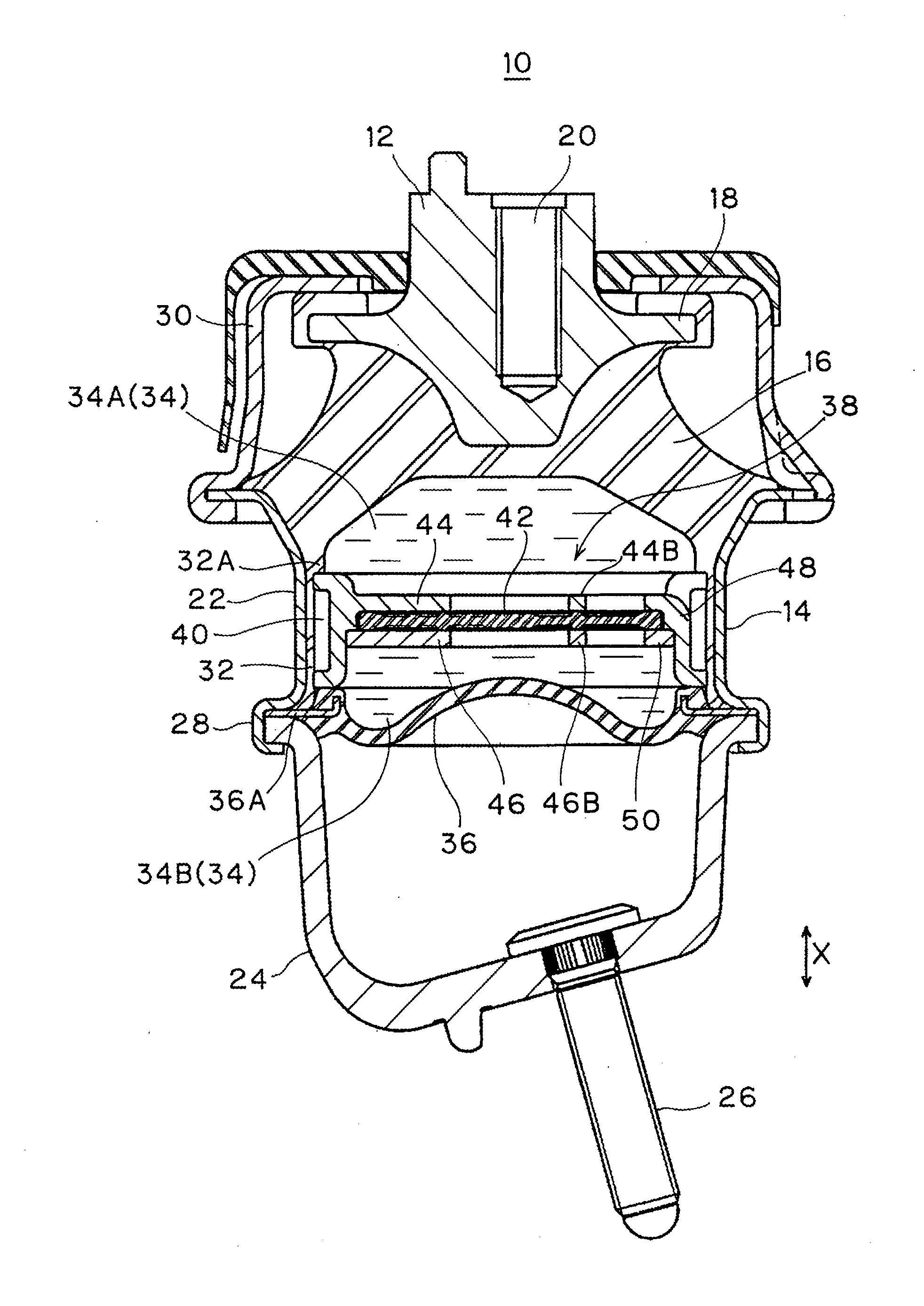
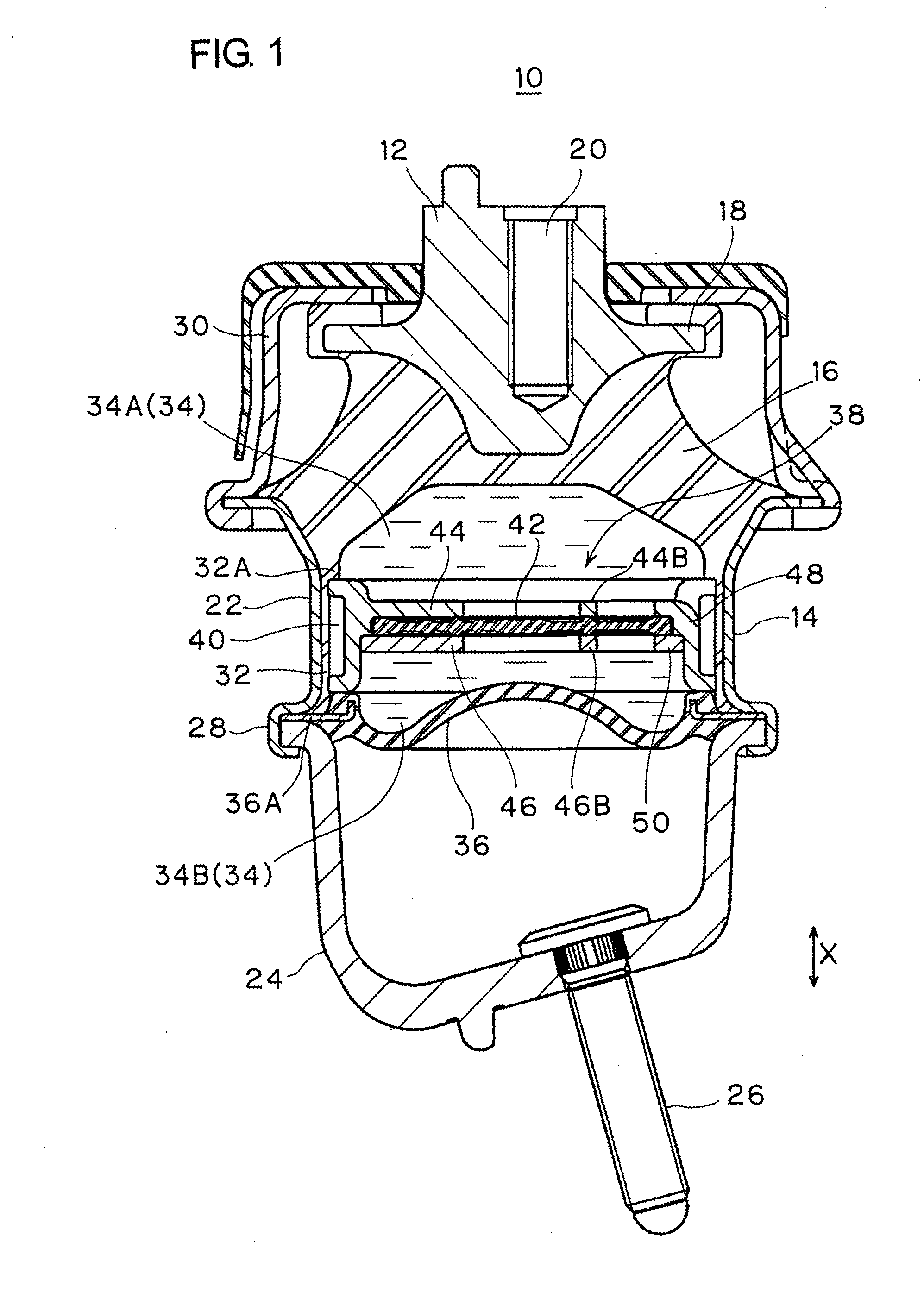
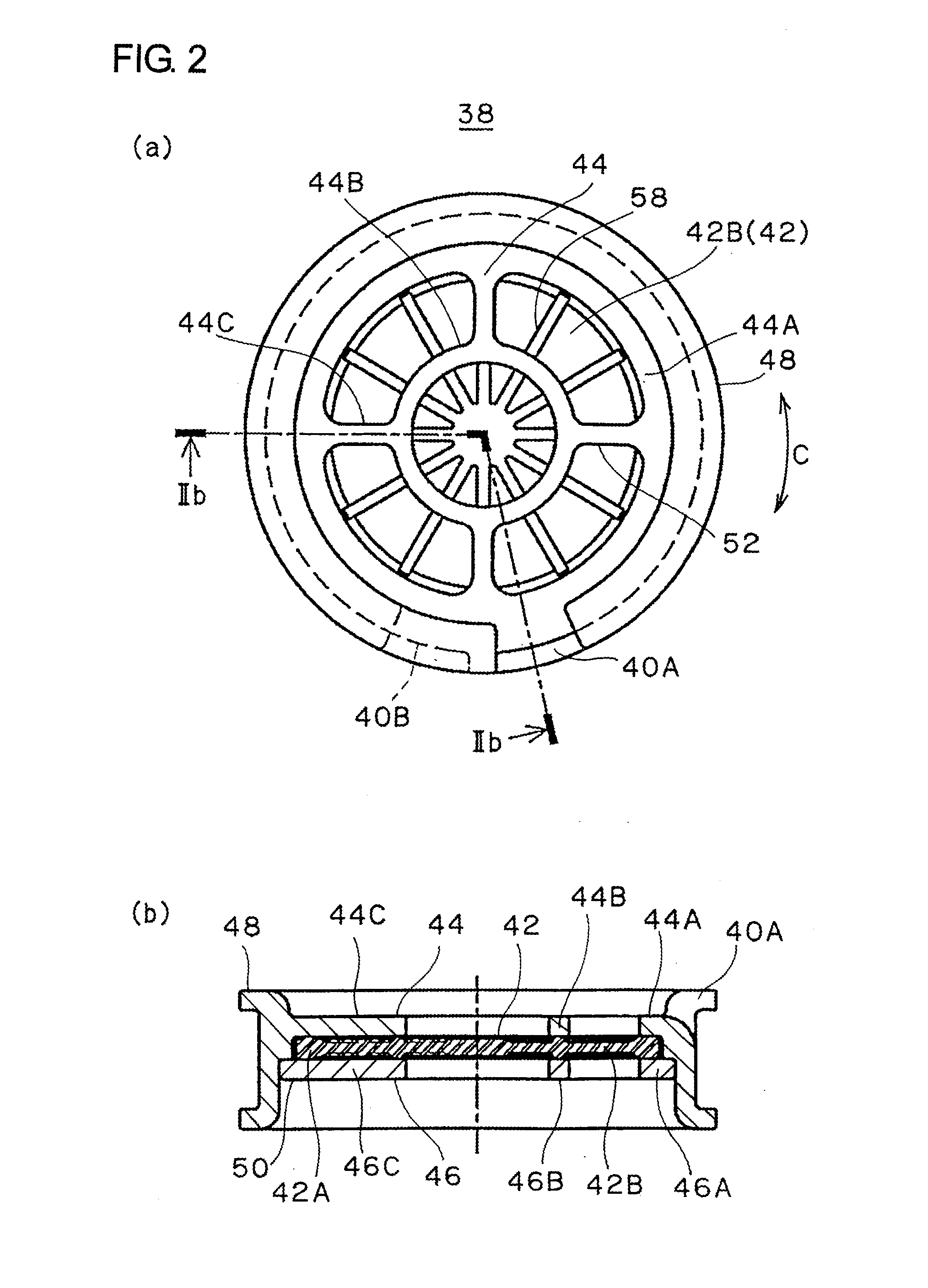
[0035]A liquid-sealed antivibration device 10 according to a first embodiment is explained in conjunction with FIG. 1 to FIG. 5. The antivibration device 10 is an engine mount for supporting an engine of an automobile. The antivibration device 10 includes: an upper-side first mounting member 12 to be mounted on an engine side which constitutes a vibration source side; a lower-side cylindrical second mounting member 14 to be mounted on a vehicle body on a support side; and a vibration-isolating base 16 made of a rubber elastic body which is interposed between both mounting members 12, 14 and connects both mounting members 12, 14 to each other.

[0036]The first mounting member 12 is a boss fitting arranged along an axis of the second mounting member 14 at an upper portion of the mounting member 14, and a stopper portion 18 which projects radially outward in a flange shape is formed on the first mounting member 12. A bolt h...

second embodiment

[0057]A liquid-sealed antivibration device 100 according to a second embodiment is explained in conjunction with FIG. 6 to FIG. 14. The liquid-sealed antivibration device 100 is an engine mount in the same manner as the first embodiment, and the respective constitutions of a first mounting member 12, a second mounting member 14, and a vibration-isolating base 16 are equal to the constitutions of the corresponding parts of the first embodiment and hence, the same symbols are given to the identical parts and the repeated explanation of these parts is omitted. In the second embodiment, using the above-mentioned diaphragm 36 as a first diaphragm, a liquid-sealed chamber 34 is defined between the first diaphragm 36 and the vibration-isolating base 16, and the liquid-sealed chamber 34 is partitioned by a partition element 140 into an upper-side main liquid chamber 34A where the vibration-isolating base 16 constitutes a portion of a chamber wall of the upper main liquid chamber 34A and a l...

example

[0094]Butyl-rubber-based rubber composition according to the embodiment is prepared in accordance with blending shown in a following Table 1 using a Banbury mixer. Further, Natural-rubber-based rubber composition according to a comparison example is prepared in accordance with blending shown in a following Table 2. Using the obtained rubber composition, the elastic membrane 42 of the above-mentioned first embodiment is formed by vulcanization molding in accordance with a normal method, and the elastic membrane 42 is assembled into the liquid-sealed antivibration device 10 of the first embodiment. Then, the abnormal sound performance is evaluated.

TABLE 1Name of raw materialparts by weightButyl rubber (“IIR268” made by Exxon Mobil 100Corportion)SRF carbon black (“SEAST S” made by50TOKAI CARBON CO., LIMITED.)Paraffin oil (“PW-380” made by Idemitsu10Kosan Co., Ltd.”)Zinc flower (“zinc oxide third class” made by5.0Seido Chemical Industry Co., Ltd.)Stearic acid (made by NOF CORPORATION)1....


PUM


Abstract

In a liquid-sealed antivibration device 10 which includes: a main liquid chamber 34A where a vibration-isolating base 16 forms a portion of a chamber wall thereof; a subsidiary liquid chamber 34B where a diaphragm 36 forms a portion of a chamber wall thereof; a partition element 38 by which the main liquid chamber 34A and the subsidiary liquid chamber 34A are partitioned from each other; and an orifice flow passage 40 which allows the main liquid chamber 34A and the subsidiary liquid chamber 34B to be communicated with each other, an elastic membrane 42 is formed on the partition element 38, and the elastic membrane 42 is formed of rubber composition containing butyl rubber or halogenated butyl rubber. Due to such a constitution, an abnormal sound generated by collision of the elastic membrane 42 is reduced.

Description

TECHNICAL FIELD[0001]The present invention relates to a liquid-sealed antivibration device.[0002]As an antivibration device such as an engine mount which supports a vibration source such as an automobile engine in a state where vibrations of the vibration source are not transmitted to a vehicle body side, there has been known a liquid-sealed antivibration device having the following constitution. That is, the liquid-sealed antivibration device includes a first mounting member which is mounted on one of a vibration source side and a support side, a second mounting member which is mounted on the other of the vibration source side and the support side, a vibration-isolating base formed of a rubber-like elastic body interposed between these mounting members, a diaphragm formed of a flexible rubber film, a main liquid chamber where the vibration-isolating base forms a portion of a chamber wall of the main liquid chamber, a subsidiary liquid chamber where the diaphragm forms a portion of ...

Claims


Application Information

Patent Timeline
Patent Type & Authority Applications(United States)
IPC IPC(8): F16F13/10F16F13/18
CPCF16F13/106
Inventor YAMAMOTO, KENTAROSAITO, KATSUSHIISAWA, GENMASUDA, TATSUNORISAKURAI, KATSUHIRO
Owner TOYO TIRE & RUBBER CO LTD
Why Eureka
Try Eureka