LC Oscillator

a technology of oscillator and phase noise, applied in the direction of varying frequency control of electrified characteristics, discontnuous tuning with seperate pre-tuned circuits, chairs, etc., can solve the problems of linearity of the variable, add to the phase noise of the oscillator, and be suitable for a small frequency tuning rang

Inactive Publication Date: 2012-03-29
QUALCOMM TECH INT
View PDF3 Cites 1 Cited by
  • Summary
  • Abstract
  • Description
  • Claims
  • Application Information

AI Technical Summary

Benefits of technology

[0011]According to an embodiment of the invention, there is provided an oscillator comprising a capacitive element and an inductive element for generating an output signal having a predetermined frequency, the capacitive element comprising two or more capacitive arrays, each array having one or more capacitors that are switchably connectable in parallel with the inductive element so as to control the frequency of the output signal, and at least one of those arrays being connected to only part of the inductive element such that, when a capacitor in said one array is connected to that part, the resulting change in the frequency of the output signal is smaller than it would have been if the capacitor had been connected to the whole of the inductive element.

Problems solved by technology

A problem with this implementation is the varactor linearity.
This is a problem for polar loop transmitters in which both a wide range of frequency tuning and good linearity are required.
In addition, the combination of a digital-to-analogue converter (DAC) and a varactor adds to the phase noise of the oscillator as the thermal and flicker noise of the DAC modulates the varactor.
This approach is therefore only suitable for a small frequency tuning range, e.g. a range of a few MHz with 1 kHz steps.
A problem with this approach is that the size of the unit capacitors can become so small that the circuit cannot be implemented in a practical sense.
The drawback is that the VCO current increases linearly with the total capacitance value.
A problem, however, with this approach is that the total capacitance seen by the inductor is not a linear function of the number of capacitors switched into the capacitive bank.
A capacitive divider does not therefore provide the linearity required for digital control of the oscillator.

Method used


Image

  • LC Oscillator
  • LC Oscillator
  • LC Oscillator

Examples


Embodiment Construction

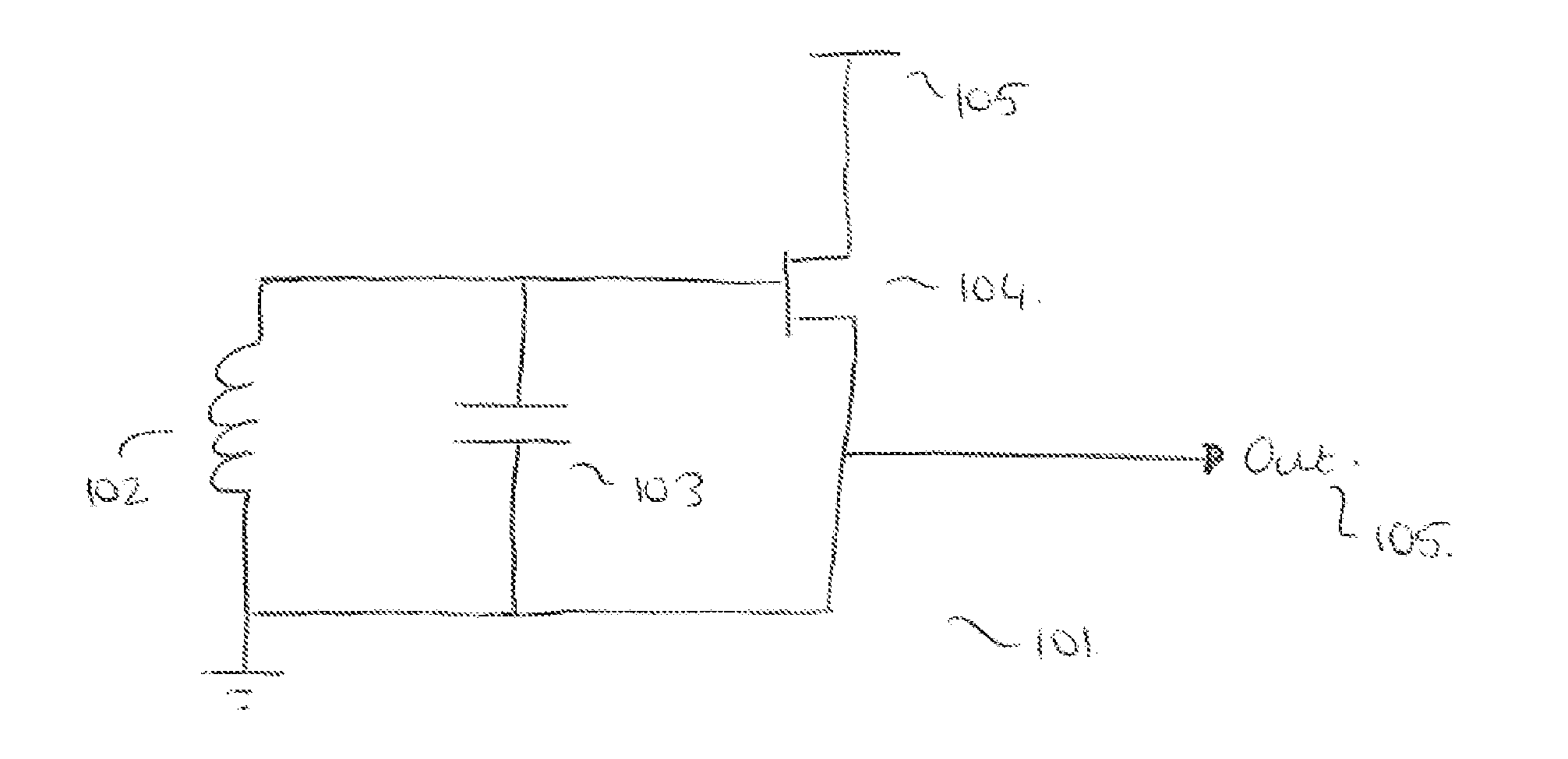
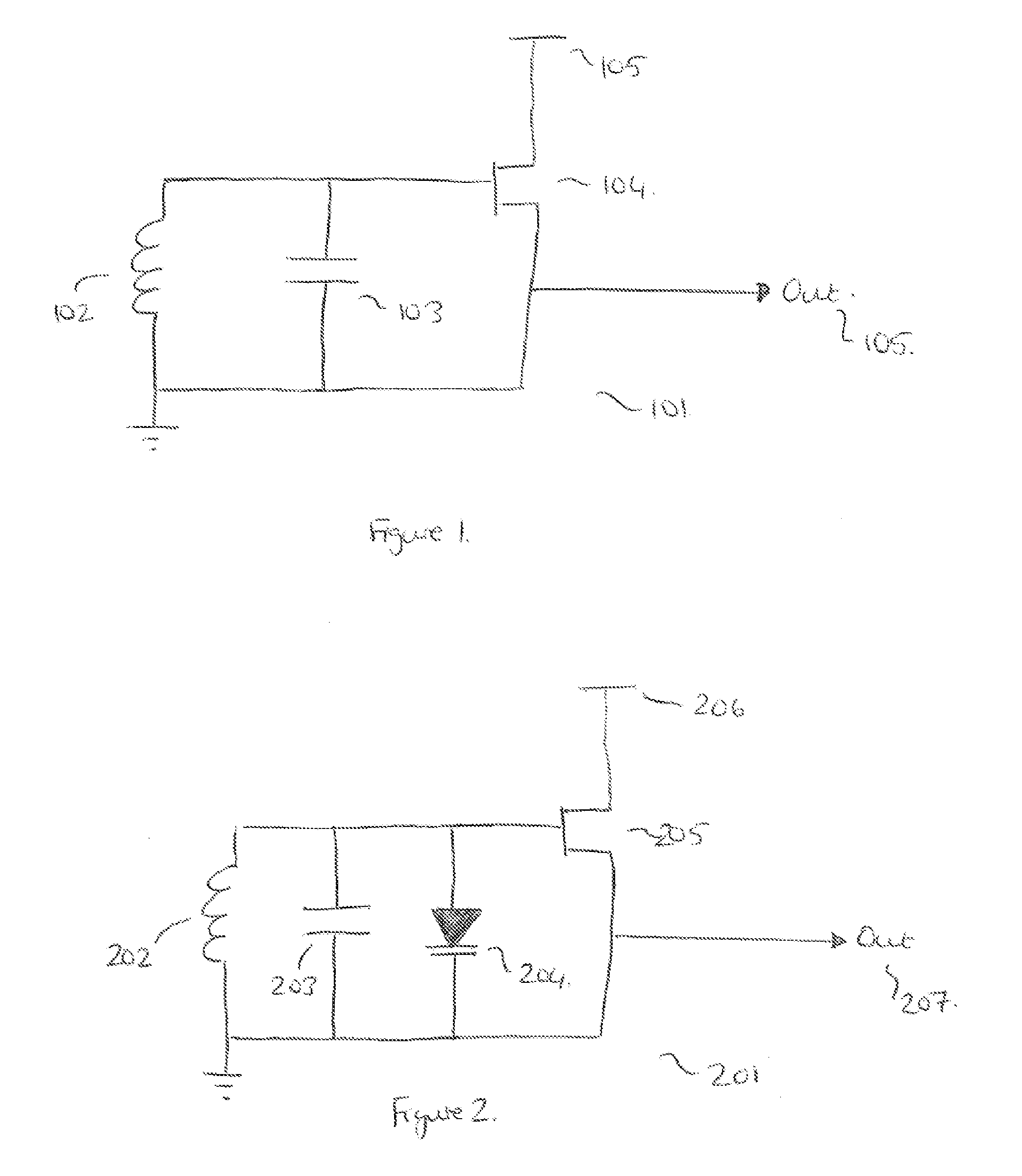
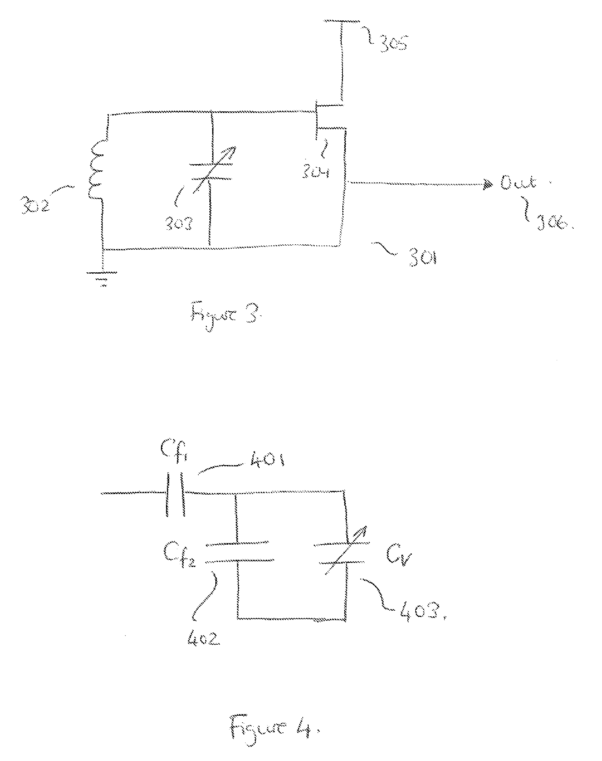
[0024]An oscillator capable of generating a signal at different frequencies within a predetermined frequency range may comprise a capacitive element and an inductive element. The capacitive element may comprise two or more capacitive arrays. Each array may include one or more capacitors switchably connectable in parallel with the inductive element so as to control the frequency of the output signal. One of the capacitive arrays may be connected to only part of the inductive element, so that it sees a smaller inductance another of the arrays. Since the effect that a particular capacitance has on the output frequency is dependent on the inductance it is connected to, connecting an array to only part of the inductance can be used to increase the size of capacitor required to achieve a particular frequency step. This is because a capacitor connected to only part of the inductance will produce a smaller change in the frequency of the output signal than it would have if the capacitor had ...


PUM


Abstract

An oscillator including a capacitive element and an inductive element for generating an output signal having a predetermined frequency, the capacitive element comprising two or more capacitive arrays, each array having one or more capacitors that are switchably connectable in parallel with the inductive element so as to control the frequency of the output signal, and at least one of those arrays being connected to only part of the inductive element such that, when a capacitor in said one array is connected to that part, the resulting change in the frequency of the output signal is smaller than it would have been if the capacitor had been connected to the whole of the inductive element.

Description

BACKGROUND OF THE INVENTION[0001]The invention relates to LC oscillators and particularly to LC oscillators that comprise a switchable bank of capacitors for adjusting the output frequency of the oscillator.[0002]A phase-locked loop (PLL) is a well known circuit for generating signals having a predetermined frequency relationship with a reference signal. In its most basic form, a phase-locked loop comprises an oscillator that is controlled by means of a feedback loop. The feedback loop takes the output of the oscillator, compares it with a reference signal and adjusts the oscillator accordingly. Typically the feedback loop comprises a divider for dividing the output signal, a phase comparator for comparing the phase of the divided signal with the reference signal and a charge pump for outputting a pulse of charge that either speeds up or slows down the oscillator, in dependence on the phase comparison. The phase-locked loop will also typically include a filter for removing spurious ...

Claims


Application Information

Patent Timeline
Patent Type & Authority Applications(United States)
IPC IPC(8): H03B5/08H03L7/099A47C1/034
CPCH03B5/1203H03B5/1212H03B5/1228H03B5/1265H03B5/1243H03B5/12H03J5/246H03L7/0991
Inventor SORNIN, NICOLAS
Owner QUALCOMM TECH INT
Why Eureka
Try Eureka