Microphone

a technology of capacitor microphone and microphone, which is applied in the direction of electrical transducers, transducer types, and semiconductor electrostatic transducers, can solve the problems of worsening the signal quality of the collective audio signal, and achieve the effect of sufficiently suppressing vibration nois

Inactive Publication Date: 2012-03-29
PANASONIC CORP
View PDF6 Cites 19 Cited by
  • Summary
  • Abstract
  • Description
  • Claims
  • Application Information

AI Technical Summary

Benefits of technology

[0012]In the field of portable communication terminals, movie cameras, digital cameras, and the like, an increasing demand exists for suppressing vibration noise. The devices are increasingly miniaturized, and there also exists a growing demand for miniaturizing components used in the devices. To meet the demands, the present invention aims at providing a capacitance microphone that lessens influence of vibration noise on a collective audio signal exerted by extraneous mechanical vibrations and that can also be miniaturized.

Problems solved by technology

When such a vibrating noise signal stemming from the extraneous mechanical vibrations is mingled with a collective audio signal, signal quality of the collective audio signal becomes worse, because the collective audio signal is faint.

Method used


Image

  • Microphone
  • Microphone
  • Microphone

Examples


first embodiment

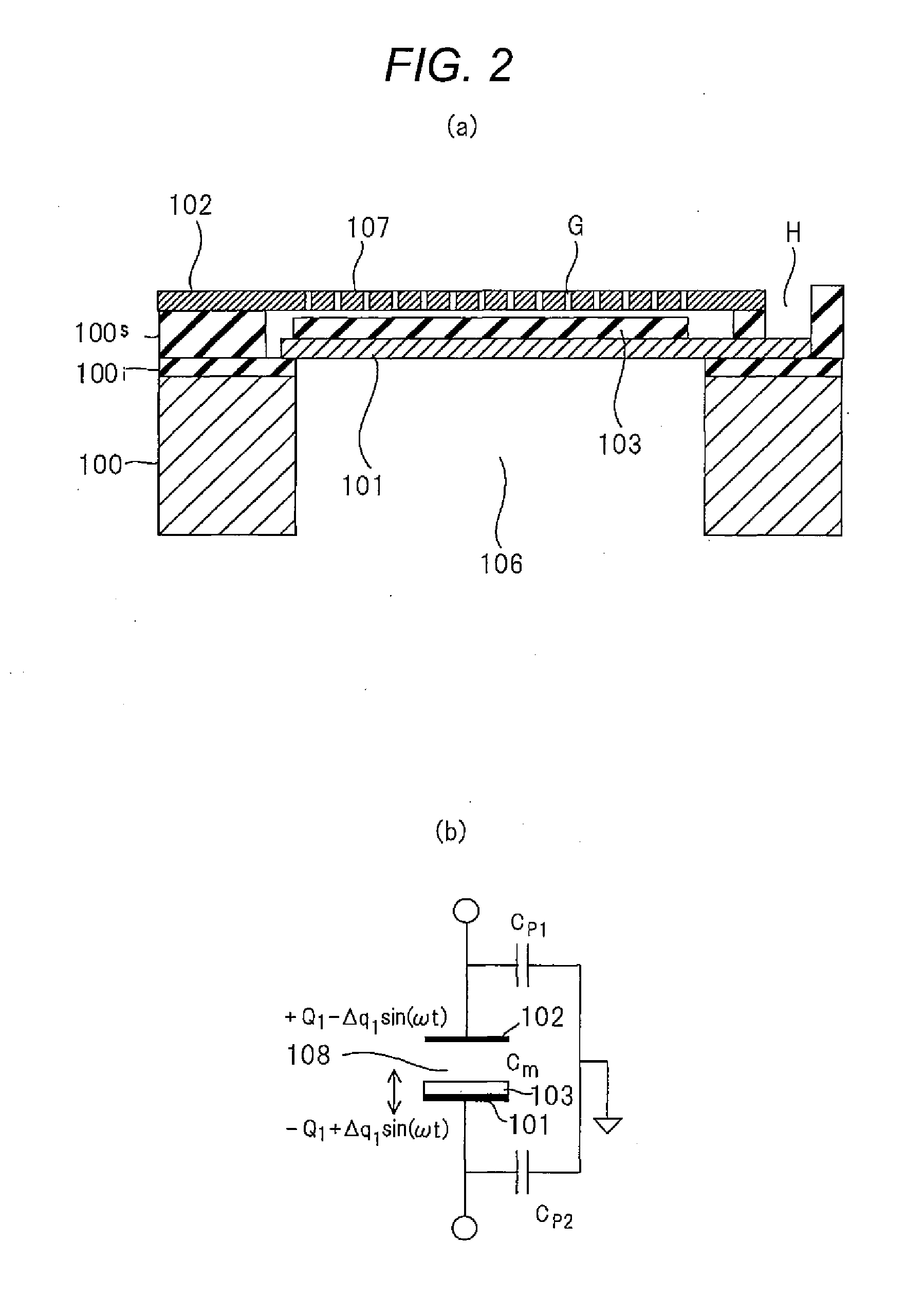
[0070]By reference to FIGS. 1 through 4, a first embodiment of the present invention is hereunder described in detail. Materials and numerals employed in the present invention are mere illustration of preferable examples, and the present invention is not limited to the embodiment. The present invention is susceptible to modifications, as required, within the scope of idea of the present invention. In addition, the embodiment can also be combined with another embodiment. A capacitance section of a capacitance microphone is an MEMS element section. In particular, explanations are hereunder provided on condition that the MEMS element section has an electret. As will be described later, the MEMS element section herein refers to a capacitor made by use of semiconductor processes. The above descriptions can be said to be common throughout the present invention.

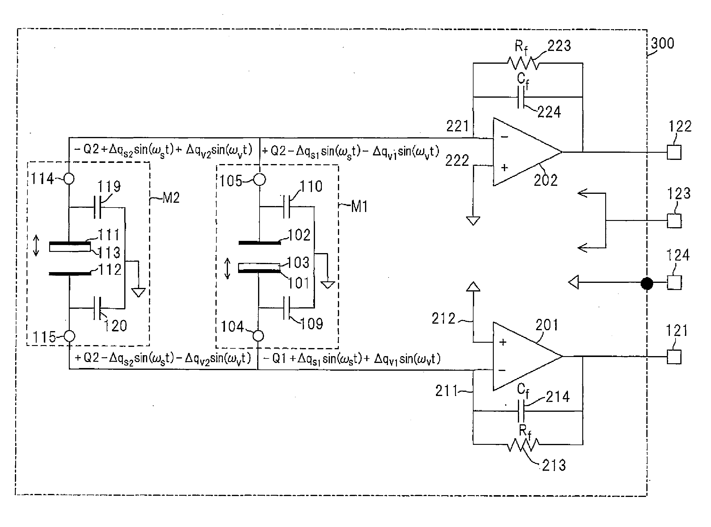
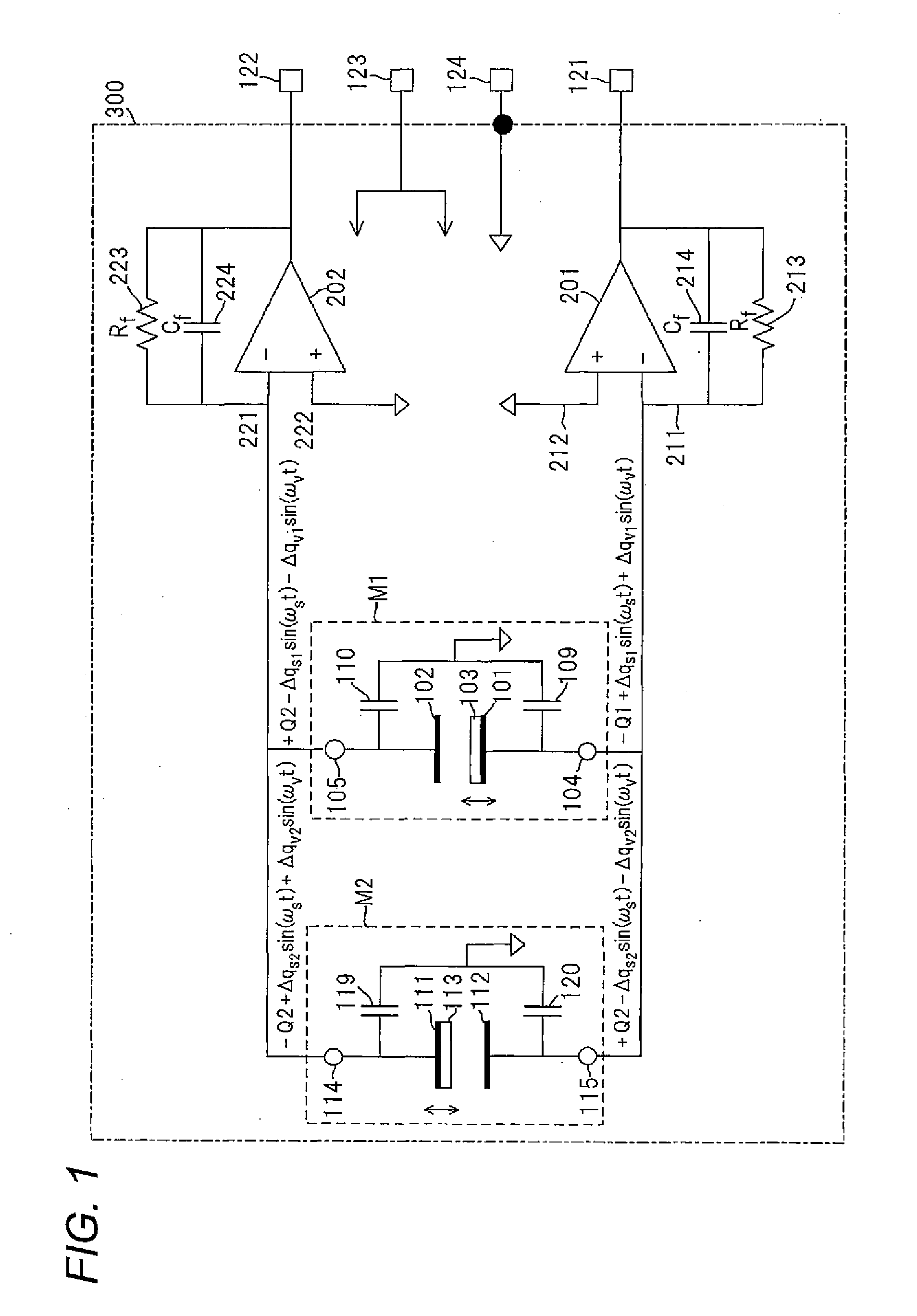
[0071]FIG. 1 is a schematic diagram of an equivalent circuit diagram of the capacitance microphone of the first embodiment of the ...

second embodiment

[0223]A second embodiment of the present invention is hereunder described in detail by reference to FIG. 10.

[0224]Materials and numerical values employed in the present invention are mere illustration, and the present invention is not limited to the illustrated mode. The present invention is susceptible to modifications, as required, without departing the scope of concept of the present invention. In addition, the present embodiment can also be used in combination with another embodiment. The capacitance section of the capacitance microphone is an MEMS element section and explained especially as an MEMS element section having an electret. As will be described later, the MEMS element section designates a capacitor fabricated by use of semiconductor processes. The above can also be said commonly through the present invention.

[0225]FIG. 10 is a schematic diagram of an equivalent circuit of a capacitance microphone of the second embodiment of the present invention.

[0226]As shown in FIG....


PUM


Abstract

There is provided a microphone that can suppress vibration noise stemming from mechanical vibrations and that outputs a collective signal having superior quality.There is provided a microphone comprising a first capacitance section M1 having a first movable electrode 101 and a second electrode 102 disposed opposite the first electrode 101 and a second capacitance section M2 that has a first movable electrode 111 and a second electrode 112 disposed opposite the first electrode 111; a first amplifier 201 that amplifies a signal from the first electrode 101 of the first capacitance section M1 and a signal from the second electrode 112 of the second capacitance section M2; and a second amplifier 202 that amplifies a signal from the second electrode 102 of the first capacitance section M1 and a signal from the first electrode 111 of the second capacitance section M2.

Description

BACKGROUND OF THE INVENTION[0001]1. Technical Field[0002]The present invention relates to a capacitor microphone and, more particularly, to suppressing vibration noise stemming from mechanical vibrations. Further, the present invention relates to a capacitance microphone that effectively utilizes electric charges developing in two mutually opposite electrodes making up a capacitance section.[0003]2. Description Related Art[0004]A capacitance section making up a capacitance microphone is a sensor that outputs an electric signal in accordance with vibration and wobbling of mutually opposite electrodes placed in the capacitance section by way of electrostatic energy. In addition to the capacitance microphone, a pressure sensor, an acceleration sensor, and the like, are available as sensors that each have capacitance sections. The capacitance microphone and the pressure sensor are sensors for sensing vibrations of the mutually opposite electrodes, while the acceleration sensor is a sens...

Claims


Application Information

Patent Timeline
Patent Type & Authority Applications(United States)
IPC IPC(8): H04B15/00
CPCH04R19/005H04R2410/03H04R19/016H01L2224/48137
Inventor KIMURA, NORIOMASAI, SHIGEONAKANOSAI, YASUHIRO
Owner PANASONIC CORP
Why Eureka
Try Eureka